


Introduction
A mining rail system operates under some of the harshest conditions in industrial rail engineering. Underground tunnels combine high humidity, corrosive water runoff, and tight clearance constraints. Open-pit mines subject their tracks to extreme loads, thermal cycling, and constant abrasive dust. In either environment, the track is not merely a transportation corridor — it is the backbone of mine productivity and safety.
A properly specified mining rail system reduces equipment failures, extends component life by 30-50%, and minimizes costly downtime. Poor selection, on the other hand, leads to rail deformation, fatigue fractures, and derailment risks that endanger both personnel and production schedules.
This guide covers everything you need to know about mining rail systems — from component selection through installation, maintenance,and troubleshooting.

Step 1: Understanding Mining Rail System Components
1.1 Steel Rails
Mining rail profiles fall into two fundamentally different categories. The table below clarifies both:
| Rail Profile | Weight (kg/m) | Standard | Application Category | Typical Use Case |
| GB 22 / GB 30 | 22 / 30 | Chinese GB | Transport rail | Light underground tramming, narrow-gauge mine cars |
| GB 38 / GB 43 / GB 50 | 38 / 43 / 50 | Chinese GB | Transport rail | Medium to heavy underground mine haulage |
| ASCE 60 / ASCE 85 | 30 / 42 | ASTM A1 (US) | Transport rail | Open-pit and underground mining railways |
| UIC 54 / UIC 60 | 54 / 60 | UIC (EU) | Transport rail | Modern heavy underground mine railways |
| A65 | 43.1 | DIN 536 (EU) | Industrial / crane rail | Underground repair shops, light crane tracks |
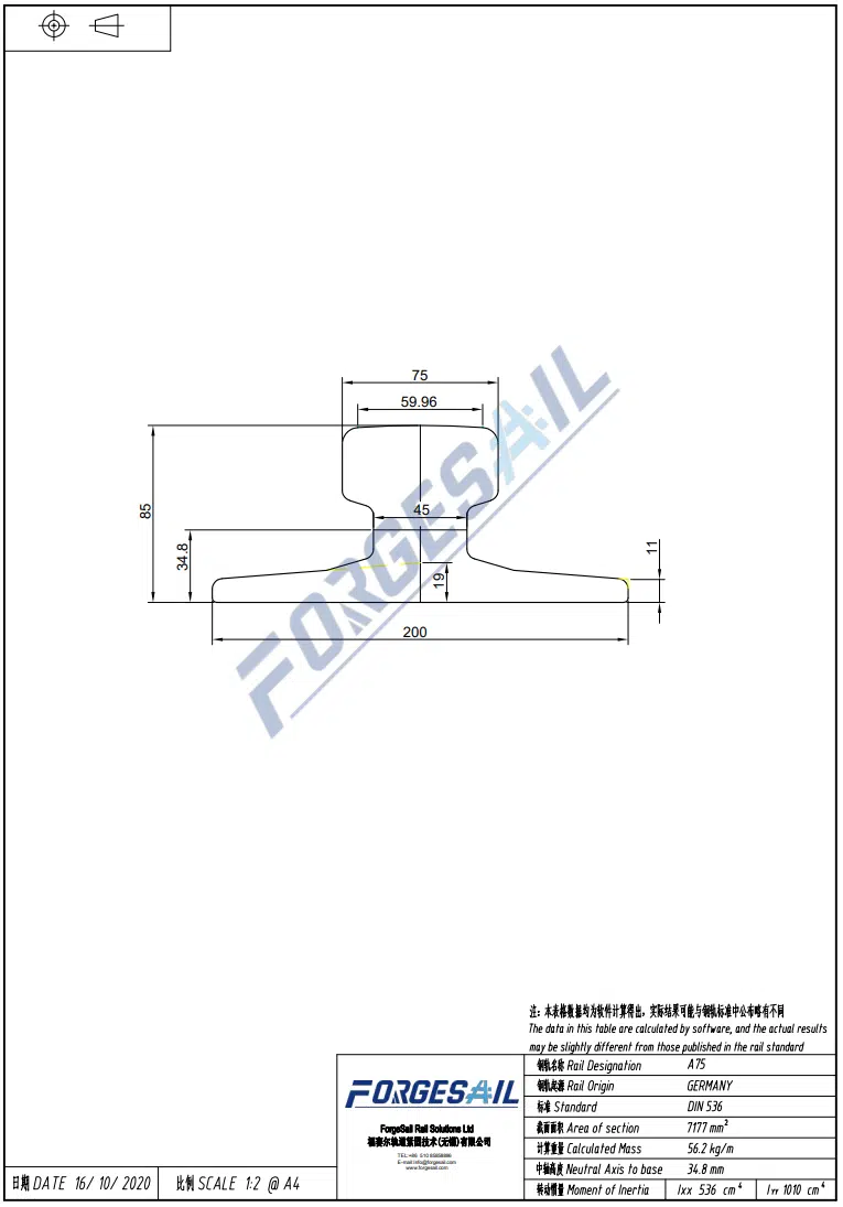
| A75 | 56.2 | DIN 536 (EU) | Industrial / crane rail | Medium crane tracks, underground loading stations |
| A100 | 74.3 | DIN 536 (EU) | Industrial / crane rail | Heavy crane tracks, main workshop bays |
| QU70 / QU80 | 52/80 | Chinese YB/T 5055 | Industrial / crane rail | Mine portal cranes, lighter industrial crane tracks |
| QU100 | 89 | Chinese YB/T 5055 | Industrial / crane rail | Heavy-duty crane tracks, large equipment yards |
| A120 | 100 | DIN 536 (EU) | Industrial / crane rail | Extreme heavy-load cranes, large-scale maintenance depots |
| 135CR | 135 | ASTM A759 (US) | Industrial / crane rail | Very heavy crane tracks, steel mill / mining depots |
1.2 Rail Clips & Fastening Systems
Rail clips secure the rail to the base plate and are among the most wear-prone components in any mining rail system. Three main types dominate the industry:
Weldable Rail Clips — Welded directly to the base plate. Preferred for high-vibration heavy-load zones because they cannot loosen over time. No bolt maintenance required.
Through-Bolt Rail Clips — Removable design, ideal for sections requiring periodic rail replacement or realignment.
Elastic Rail Clips — Absorb dynamic impact through elastic deformation, reducing stress transmitted to the rail foot and base plate.

1.3 Base Plates (Sole Plates)
Base plates transfer the vertical and lateral loads from the rail into the foundation or sub-structure. For mining environments, plates must offer:
- Sufficient thickness and strength (typically 20-30mm steel plate)
- Corrosion protection — hot-dip galvanizing or epoxy coating for underground acidic conditions
- Precision-machined surfaces to match the rail foot profile
1.4 Grouts
The gap between base plates and concrete foundations must be filled with high-performance grout. Mining-grade grout requirements include:
• Early high strength: ≥ 50 MPa compressive strength at 24 hours
• Non-shrink / micro-expansion: Ensures full contact between plate and foundation
• Chemical resistance: Resists acidic mine water and sulfate attack
1.5 Buffer Stops
Every track dead-end requires a buffer stop to prevent vehicles from running off the rail. Mining buffer stops must be engineered to absorb the kinetic energy of fully loaded trains at operating speeds. Polyurethane and hydraulic buffer designs are common for mining applications.
1.6 Aluminothermic Welding Kits
For open-pit mines and non-gaseous environments, welded joints are strongly recommended over fishplate connections in mining rail systems. Aluminothermic welding produces a continuous rail surface with superior strength and smoother running characteristics, significantly reducing dynamic impact at joint locations. However, in underground coal mines where explosive gases (methane) may be present, open-flame aluminothermic welding is prohibited by safety regulations in most jurisdictions. In those environments, heavy-duty fishplates (joint bars) must be used instead, in compliance with applicable mining safety codes.
View our complete range of mining rail system components → (/products/)

____________________________________________________________
Step 2: Selecting the Right Mining Rail System for Your Operation
2.1 Underground vs. Open-Pit Mining
| Factor | Underground Mine | Open-Pit Mine |
| Space | Tight tunnels, sharp curves | Open terrain, long straight runs |
| Corrosion | High humidity, acidic water | UV exposure, rain, thermal cycling |
| Grade | Often steep (3‰–5‰ inclines) | Generally gentle slopes |
| Haulage Pattern | Multi-car train cycles | Single large-unit shuttles |
| Maintenance Access | Limited time windows, confined space | Easier access and equipment mobility |
Underground mines benefit from A75 or A100 rails with weldable clips and corrosion-resistant base plates.
Open-pit mines typically require QU100 or DIN 536 heavy rails with high-strength grout and elastic clip systems.
2.1.1 Mining Transport Rails vs. In-Mine Industrial & Crane Rails
A common point of confusion in mining rail system selection is the difference between transport rails and industrial/crane rails. While both can appear within a mine site, they serve fundamentally different purposes.
Mining Transport Rails (Vignole / flat-bottom profiles)
- Designed for rolling stock — mine cars, locomotives, and ore wagons
- Standard T-section (Vignole) profile with narrower head and tapered web
- Rail head profile is shaped to match standard mining wagon wheel flanges
- Examples: GB 22 / GB 30 / GB 38 / GB 43 / GB 50, ASCE 60 / ASCE 85, UIC 54 / UIC 60
In-Mine Industrial & Crane Rails
- Designed for stationary or traveling cranes, transfer cars, and workshop equipment
- Wide flat head, thick web, and wide base — optimized for high point-loads from crane wheels, not for flanged wagon wheels
- Found in: maintenance bays, underground loading pockets, portal crane tracks, heavy equipment laydown yards
- Examples: DIN 536 A65 / A75 / A100 / A120, Chinese YB/T 5055 QU70 / QU80 / QU100, ASTM A759 135CR / 175CR
⚠️ Critical distinction: Mine car wheel flanges are designed for Vignole (T-section) rail heads and **cannot safely run** on the wide, flat head of DIN 536 A-Series or QU-Series crane rails. Using crane rails for haulage track creates a serious derailment hazard.
Selection rule of thumb: If it carries people or ore between mine zones, use transport rails. If it supports stationary lifting or workshop equipment within a single facility, use industrial/crane rails. Choosing the wrong type leads to premature wear, poor wheel-rail interface performance, and accelerated maintenance costs.
2.2 Load Volume Determines Rail Grade
A practical guideline: daily tonnage exceeding 10,000 tonnes demands UIC 60, ASCE 85, or GB 50 transport rail profiles. Operations moving 3,000–10,000 tonnes per day can work with UIC 54, ASCE 60, or GB 43. Light auxiliary transport is adequately served by GB 22 or GB 30.
| Daily Mine Haulage Tonnage | Recommended Transport Rail (Int’l) | Matching Domestic Rail | Mine Application Scenario |
| Below 3,000 MT / day | ASCE 60 | GB 22 / GB 30 | Underground auxiliary tunnels, small mine branch lines, light mine cars |
| 3,000 – 10,000 MT / day | UIC 54 / ASCE 85 | GB 43 | Medium underground main haulage, medium open-pit side tracks |
| Over 10,000 MT / day | UIC 60 | GB 50 | Heavy-duty underground trunk lines, primary open-pit mine haulage |
2.3 Material Selection for Corrosive Environments
For underground conditions with pH below 5:
- Base plates should use stainless-clad or hot-dip galvanized steel
- Rail clips benefit from alloy steel with anti-corrosion coating
- Grout selection should favor acid-resistant epoxy formulations
2.4 Foundation Conditions
• Concrete slab: Surface flatness tolerance ≤ ±3mm per meter
• Ballast bed: Crushed stone depth ≥ 250mm, aggregate size 25–60mm
• Steel-fiber reinforced concrete: Recommended for high-impact zones with frequent heavy loading
____________________________________________________________
Step 3: Choosing Compatible Rail Fastening Components
The rail fastening system. View our heavy-duty rail clips for mining applications is the most maintenance-critical element of any mining rail system. Here are the selection criteria:
3.1 Clamping Force Requirements
Each rail clip must deliver sufficient clamping force to resist rail rollover under lateral load while allowing for thermal expansion. For standard mining rail profiles, clamping force typically ranges from 8 kN to 25 kN per clip, depending on clip design and rail size.
3.2 Clip Spacing
Standard clip spacing for mining rail is 500–600mm centers. Closer spacing (400mm) is recommended for tight curves where lateral forces are higher. Wider spacing (up to 700mm) is acceptable on straight, low-speed sections.
3.3 Base Plate Geometry
The base plate bearing surface must match the rail foot profile precisely. A mismatch of even 1–2mm can create stress concentrations that lead to rail foot cracking under cyclic loading.
Compare our weldable vs. bolt-down rail clip options.
____________________________________________________________
Step 4: Mining Rail Installation — Step by Step
4.1 Foundation Inspection
Before installation, verify:
- Concrete has reached ≥ 80% of design strength
- Anchor bolt positions are within ±2mm of design coordinates
- Foundation surface is free of laitance, cracks, and debris
4.2 Track Laying Sequence
1. Survey and mark — Establish centerline and elevation benchmarks every 5m on straight sections
2. Position base plates — Set plates on levelling shims at the correct elevation
3. Grouting — Inject high-strength grout to fill the gap between plate and foundation completely
4. Rail placement — Use rail clamps or a crane to position rails on the base plates
5. Aluminothermic welding — Join rail sections into continuous lengths first, while the rails are still free to move longitudinally on their base plates
6. Stress neutralization — Calculate and set the correct stress-free temperature. At this stage the rails must be free to expand or contract (or be hydraulically tensioned) to reach the design stress state. The clips must NOT be fully locked before this step is complete
7. Clip final installation — Once the rail is in a stress-free state at the correct temperature, tighten all clip bolts to final torque immediately to lock the rail in position. (For weldable clips, the clip bases may be welded to the plate in advance, but the clamping tongues should not be fully tightened until after stress neutralization.)
8. Buffer stop installation — Mount and anchor the buffer stops at track ends
4.3 Acceptance Tolerances
- Gauge tolerance: ±2mm
- Cross-level tolerance: ±3mm
- Alignment (straight sections): ±2mm per 10m
- Surface profile: ±3mm per 10m
- Weld quality: 100% ultrasonic inspection pass
____________________________________________________________
Step 5: Mining Rail Track Maintenance — A Practical Schedule
5.1 Daily Visual Inspection
- Check rail running surface for cracks, spalling, or head checking
- Verify clips are intact and properly seated
- Listen for abnormal wheel noise during passage
- Inspect buffer stop condition
5.2 Weekly & Monthly Checks
| Inspection Item | Frequency | Method |
| Gauge measurement | Weekly | Gauge ruler |
| Rail head wear | Monthly | Head profile gauge or caliper |
| Grout integrity | Monthly | Hammer-sound test for hollow areas |
| Weld condition | Quarterly | Ultrasonic flaw detection |
| Base plate settlement | Quarterly | Level survey |
| Clip torque / tightness | Monthly | Torque wrench check |
5.3 Seasonal Maintenance
• Before rainy season: Check drainage, clear water accumulation along the track
• Before winter: Verify expansion gaps are adequate, remove snow and ice buildup
• During high-heat periods: Monitor rail stress to prevent buckling
5.4 Replacement Thresholds
| Component | Replacement Criteria |
| Rail | Vertical head wear ≥ 8mm OR side wear ≥ 12mm |
| Rail Clip | Cracked, severely deformed, or clamping force dropped by > 30% |
| Base Plate | Corrosion thinning ≥ 3mm OR visible cracking |
| Grout Layer | Hollow area > 20% OR crack width > 1mm |
____________________________________________________________
Step 6: Common Mining Rail System Problems & Solutions
6.1 Rail Shelling
• Cause: Excessive contact stress, insufficient lubrication
• Solution: Reduce axle load, improve lubrication regime, schedule periodic head grinding
6.2 Gauge Widening
• Cause: Loose clips, base plate creep
• Solution: Replace or re-torque clips, inspect and reposition base plates
6.3 Rail Corrugation
• Cause: Wheel-rail resonance, frequent braking and traction cycles
• Solution: Rail grinding, optimize traction patterns, consider elastic fasteners
6.4 Grout Deterioration
• Cause: Poor-quality material, uneven foundation settlement
• Solution: Remove deteriorated grout, re-pour with high-strength mining-grade grout
6.5 Buffer Stop Failure
• Cause: Cumulative fatigue, incorrect installation angle
• Solution: Replace with fatigue-rated buffer, verify alignment and anchoring
____________________________________________________________
Step 7: Why Partner with ForgeSail for Your Mining Rail System
ForgeSail is a manufacturer-backed supplier of complete mining rail systems. Here is what sets us apart:
Factory-Direct Quality
We own the full production chain — from rail processing and clip fabrication to grout manufacturing. Every batch is fully traceable, giving you consistent quality and direct cost control.
One-Stop Component Supply
Rails, clips, base plates, grouts, buffer stops, and aluminothermic welding kits — everything from a single source, reducing procurement complexity and lead times.
EPC Project Experience
We have delivered mining rail system projects across multiple countries, handling everything from design selection through site installation and acceptance testing.
Custom Engineering
Standard profiles do not always fit mining-specific conditions. We offer tailored rail profiles, custom clip geometries, and specialized corrosion protection — matched to your underground or open-pit environment.
Read more about railway track engineering fundamentals
____________________________________________________________
Conclusion
A mining rail system is a long-term investment that directly impacts haulage efficiency, safety, and operating costs. Getting it right starts with understanding the load environment, selecting compatible components, installing to precise tolerances, and maintaining a disciplined inspection schedule.
Whether you are building a new mining rail system or upgrading an existing track, working with an experienced supplier who understands mining-specific requirements makes the difference between a system that simply functions and one that delivers maximum uptime.