



BHDA Adjustable Heavy-Duty Buffers — Air-Bag Return with 1–5 Step On-Site Tuning
Everything the BHD platform does, plus an adjustment knob. One heavy-duty model can cover several work stations with different loads.
What the BHDA Series Is For
BHDA takes the BHD air-bag platform and adds an adjustment assembly. You keep the short body and the low recoil of the nitrogen return, and you gain the ability to retune the damping force on site.
The practical benefit is inventory. A single BHDA model can cover several work stations with different loads, which cuts the number of heavy-duty sizes you have to stock — and it removes the risk of ordering a factory-set unit against a load estimate that turns out to be wrong.
The adjustment range is narrower than BHD 's stroke and energy envelope: BHDA covers 50 to 300 mm of stroke and up to 224 kJ per cycle. Beyond that, BHD is the right call.
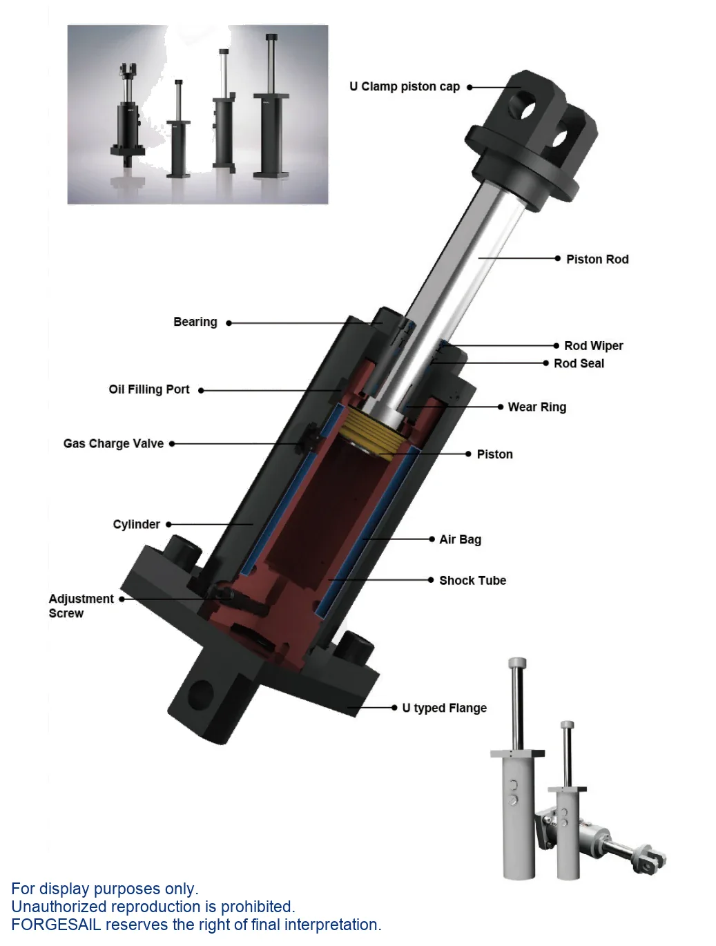
Air-Bag Return with an Adjustment Sleeve
The nitrogen bladder handles the return exactly as it does in the BHD series. On top of that, an adjustable sleeve meters how much oil bypasses the orifice stack at each step. Step 1 gives the lightest damping and the highest impact velocity; step 5 gives the heaviest damping and the lowest.
Performance &Advantages
OSHA / AISE / CMMA / DIN / FEM compliant. Special epoxy-painted cylinder and hard-chrome-plated piston rod for outdoor and corrosive service. 60 cycles/hour maximum.
1–5 step adjustment
Tune the damping force on site as the load or speed changes.
One model, several stations
Cuts heavy-duty spare-part inventory and removes the risk of a wrong factory setting.
Air-bag return
Short body and very low recoil, inherited from the BHD platform.
Certified design
Meets OSHA, AISE, CMMA, DIN and FEM requirements.
60 cycles per hour
Maximum cycle rate across the adjustment range.
Outdoor and corrosive duty
Special epoxy paint system and hard-chrome-plated piston rod as standard.
-35 °C to 100 °C
With the special seal and hydraulic oil package, up from -10 °C to 60 °C.
Model Selection
Select by stroke and energy per cycle, then confirm with the maximum energy per hour. If your duty cycle is demanding, send us the numbers and we will run the calculation for you.

| Model Group | Stroke Range (mm) | Max Energy/Cycle (Nm) | Cylinder Ø (mm) |
|---|---|---|---|
| BHDA3.0 | 50 – 300 | 9,600 – 50,700 | Ø130 |
| BHDA4.0 | 50 – 250 | 15,100 – 67,500 | Ø200 |
| BHDA5.0 | 100 – 300 | 46,700 – 140,000 | Ø215 |
| BHDA6.0 | 100 – 300 | 76,500 – 224,000 | Ø275 |
| No model matches that search. | |||
Model group shown as BHDA <bore >×<stroke >. Add the mounting code (FF / FR / TF / FM / CM) and options (SC / SS / PB). Standard fill is ISO VG 46 hydraulic oil.
How to Set the Adjustment Step
- Loosen the locking screw firstThe adjustment nut cannot move until the locking screw is released.
- Set step 1Always begin at the lightest setting.
- Increase one step at a time1 → 2 → 3 → 4 → 5, checking the stopping behaviour after each change.
- Tighten the locking screwIf it is left loose, the nut rotates under impact and the step drifts.
Always start at step 1
Starting from a high step will overload and damage the buffer. Step 1 is the lightest damping and the highest impact velocity; step 5 is the heaviest and the slowest.
Mounting Arrangements &Accessories
Five standard mounting arrangements. Add SC for a safety chain, SS for a rod-return position sensor, or PB for a piston rod bellow.
Accessories
Installation &Maintenance
- Use the buffer as an end stop.
- Remove the steel strike head.
- Exceed the permitted side load angle.
- Paint the piston rod or the body.
- Place it near acids, solvents or soluble cutting oil.
- Expose it to open flame — the unit is oil filled.
- Side load angle: below 2.5° at strokes up to 300 mm, below 1° above 300 mm.
- Never use the buffer as an end stop — fit a stop collar 1 mm before end of travel.
- Always tighten the locking screw after every adjustment.
- Parallel buffers must be the same model, with the knob on the same step.
- Inspect every 6 months on safety and emergency duty, monthly in frequent service.
Send Us Five Numbers — Get a Sizing Report in 48 Hours
Every BHDA unit is configured against your application data. Give us these five values and our engineers will return a recommended model with verified shock-force versus stroke and deceleration versus stroke curves. Free, and with no commitment to buy.
- W kg · moving weight
- V m/s · impact velocity
- Fp N · driving force
- n pcs · buffers in parallel
- Cycles / hour
BHDA Series FAQ
Part of a Complete Crane Rail System
Hydraulic buffers are one component we supply. The same engineering and manufacturing team also delivers the rest of the runway system:
- Crane rails — rail sections for crane runway systems
- Rail clips — bolted and welded fastening systems
- Rail pads — vibration and impact damping
- Sole plates — rail support and load distribution
- Rail grouts — cementitious bedding for rail fixings
- Custom machining — molds and precision machined parts
Talk to an Engineer
Tell us your application and we will come back with a recommendation, a sizing calculation and a quotation. If you are still at the design stage, we are happy to work from drawings.

