



BD Series

BD Adjustable Hydraulic Buffers — 6 to 21,000 Nm, Tuned On Site in 12 Steps

The general-purpose industrial shock absorber. Turn the adjustment knob to retune the damping force whenever your load or speed changes — one model can cover several work stations.

6 – 21,000 NmEnergy per cycle
7 – 250 mmStroke range
M10 – M115Cylinder thread
0 – 12Adjustment steps
5 daysStock lead time
Overview

What the BD Series Is For

BD is the workhorse of the range. It carries the widest stroke and energy spread of any series we supply, from a 6 Nm M10 unit for a robotic cell to a 21,000 Nm M115 unit for a heavy conveyor stop.

What sets it apart is the external adjustment knob. Twelve discrete steps let you retune the damping force on site, without tools and without removing the buffer. That matters during commissioning, when the real load is rarely the load on the drawing — and it keeps paying off afterwards, because a single model can serve several stations with different weights.

Every BD unit uses a multi-orifice damping stack rather than the single orifice used by most European and American brands. Under identical conditions this produces a lower peak damping force and completes the deceleration in less time.
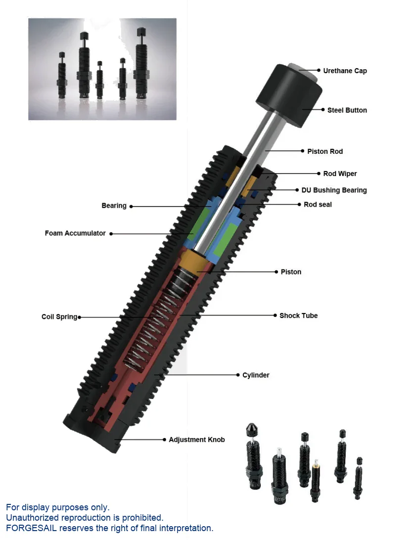
BD Adjustable Hydraulic Buffers — exploded view of internal components
>
Energy Absorption

Internal Coil Spring, Multi-Orifice Damping

Oil is metered through a stack of calibrated orifices as the piston is driven into the cylinder. The viscous resistance converts kinetic energy into heat, which is dissipated through the body. An internal coil spring returns the rod. The multi-orifice layout spreads the pressure drop across the stroke, which flattens the deceleration curve and lowers the peak force your structure has to carry.

impactpistonspringorifices
Figure. Internal Coil Spring, Multi-Orifice Damping — schematic cross-section, not to scale. Dimensional drawings and 3D STEP files are supplied with every quotation.
Performance

Performance &Advantages

Standard operating range -10 °C to 80 °C, extended to -30 °C to 100 °C with the special seal and hydraulic oil package.

01

0–12 step adjustment

Visible knob, factory set to step 6, retuned on site at any time.

02

Multi-orifice design

Lower peak damping force and a shorter stopping time than a single-orifice unit of the same size.

03

M10 to M115

Body and adjustment knob are geometrically matched so the unit stays easy to mount and easy to tune.

04

Sealing

From M20 upward: polyurethane rod seal plus wiper, running on a high-strength chrome-plated rod.

05

Side-load bearing

Long front bearing with a DU bushing carries side loads and relaxes the alignment tolerance.

06

-SP variants

BD25-25SP and BD36-25SP tolerate a 30° side load angle for rotating stations — no adapter needed.

07

Wide temperature range

-10 °C to 80 °C as standard; -30 °C to 100 °C with the special seal and oil package.

Model Selection

Model Selection

Select by stroke and energy per cycle, then confirm with the maximum energy per hour. If your duty cycle is demanding, send us the numbers and we will run the calculation for you.

BD Adjustable Hydraulic Buffers — engineering data: dimensions, stroke and energy ratings
ModelStroke (mm)Max Energy/Cycle (Nm)Max Energy/Hour (Nm/h)Cylinder Dia.
BD10-07(B)7614,500M10×1.0
BD12-10(B)101624,500M12×1.0
BD12-14(B)142235,500M12×1.0
BD14-12(B)122846,500M14×1.5
BD16-12(B)123355,000M16×1.5
BD20-16(B)165565,000M20×1.5
BD25-25(B)25220111,000M25×1.5
BD25-25(B)-SP25220111,000M25×1.5
BD25-40(B)40300182,000M25×1.5
BD25-80(B)80390210,000M25×1.5
BD27-25(B)25220111,000M27×3.0
BD27-40(B)40300182,000M27×3.0
BD30-35(B)35390210,000M30×1.5
BD33-25(B)25500120,000M33×1.5
BD33-50(B)50500150,000M33×1.5
BD36-25(B)25550125,000M36×1.5
BD36-50(B)50550160,000M36×1.5
BD42-25(B)25700185,000M42×1.5
BD42-50(B)501,350255,000M42×1.5
BD42-75(B)752,100285,000M42×1.5
BD45-25(B)25700185,000M45×1.5
BD45-50(B)501,350255,000M45×1.5
BD45-75(B)752,100285,000M45×1.5
BD64-50(B)502,500250,000M64×2.0
BD64-100(B)1005,000350,000M64×2.0
BD64-150(B)1507,500450,000M64×2.0
BD85-50(B)502,500380,000M85×2.0
BD85-90(B)904,300680,000M85×2.0
BD85-125(B)1256,0001,000,000M85×2.0
BD85-165(B)1657,5001,300,000M85×2.0
BD115-50(B)504,0001,600,000M115×2.0
BD115-100(B)1008,0001,850,000M115×2.0
BD115-150(B)15012,0002,200,000M115×2.0
BD115-200(B)20016,0002,500,000M115×2.0
BD115-250(B)25021,0002,800,000M115×2.0
No model matches that search.
← Swipe to see all columns →

LR long-return and -SP side-load variants are available on selected sizes. Suffix (B) = steel strike head; NB = supplied without strike head.

Set-Up

How to Set the Adjustment Step

  1. Start at step 0Confirm the knob is at 0 before mounting the buffer, then start the machine.
  2. Step up one notch at a time0 → 1 → 2 → 3 → 4. Never skip a step.
  3. Read the stopping behaviourSmooth deceleration with only a soft hiss at the end of travel means the step is correct.
  4. Too soft?No visible deceleration and a bang at the end of travel — the damping is too light. Increase one step.
  5. Too hard?The load stops abruptly mid-stroke with a loud report — the damping is too heavy. Decrease one step.
  6. Lock itOnce the step is right, tighten the locking screw with a hex key. A loose screw lets the nut rotate under impact.
  7. Still not right?At step 0 still overrunning means the model is too small. At step 12 still stopping hard means it is too large.

Never jump steps

Always step the damping up one notch at a time — 0 → 1 → 2 → 3 → 4. Jumping straight from 0 to 4 damages the buffer.

Installation &Maintenance

Installation &Maintenance

Never do this
  • Use the buffer as an end stop.
  • Remove the steel strike head.
  • Exceed the permitted side load angle.
  • Paint the piston rod or the body.
  • Place it near acids, solvents or soluble cutting oil.
  • Expose it to open flame — the unit is oil filled.
Do this
  • Side load angle must stay below 2°. -SP variants tolerate up to 30°.
  • Never use the buffer as an end stop — fit a stop collar 1 mm before end of travel and never remove the steel strike head.
  • Parallel buffers must be the same model, with the knob on the same step.
  • Do not paint the piston rod, and do not paint over the body — it needs to shed heat.
  • Inspect monthly in frequent service, every 6 months on safety and emergency duty.
What We Need From You

Send Us Five Numbers — Get a Sizing Report in 48 Hours

Every BD unit is configured against your application data. Give us these five values and our engineers will return a recommended model with verified shock-force versus stroke and deceleration versus stroke curves. Free, and with no commitment to buy.

  • W kg · moving weight
  • V m/s · impact velocity
  • Fp N · driving force
  • n pcs · buffers in parallel
  • Cycles / hour
FAQ

BD Series FAQ

Start at 0 and step up one notch at a time. The correct setting gives smooth deceleration over the full stroke with only a soft hiss at the end. If the load sails through and bangs, go up a step. If it stops abruptly mid‑stroke with a loud report, go down a step. Then tighten the locking screw.
BD is adjustable — twelve steps, tuned on site. BC is self‑compensating, with the orifice pattern fixed at the factory for one load class. BC absorbs more energy in the same envelope and costs less, but the setting cannot be changed later. Choose BD if your conditions vary or you are still commissioning.
Standard BD units are limited to a 2° side load angle. For rotating stations, use BD25‑25SP or BD36‑25SP, which tolerate up to 30°, or fit an SL side‑load adapter.
Side‑load protected. These variants use a reinforced front bearing and rod assembly that tolerate a 30° side load angle without bending the rod or blowing the seal.
BD and BC ship from stock within 5 business days. Heavy‑duty series are built to order against your application data, typically 4 to 6 weeks.

Talk to an Engineer

Tell us your application and we will come back with a recommendation, a sizing calculation and a quotation. If you are still at the design stage, we are happy to work from drawings.

滚动至顶部
ENFRESRU