



BC Self-Compensating Hydraulic Buffers — 10 to 680 Nm in the Smallest Envelope
Fixed orifice pattern, set at the factory for one load class. Maximum energy absorption per unit of volume, and the lowest unit price in the range.
What the BC Series Is For
BC does one job and does it very well. With no adjustment mechanism to package, the series absorbs more energy than a comparable adjustable unit of the same size — in our testing, more than 200 % of the capacity of competing products in the same envelope.
The trade-off is that the orifice pattern is fixed at the factory. You tell us the effective weight and impact velocity, and we select the pattern. Once built, the setting cannot be changed.
To keep selection simple, every BC model is offered in three hardness grades — -1 (Soft), -2 (Middle) and -3 (Hard) — matched to an effective weight range. Pick the grade, pick the stroke, and you are done.
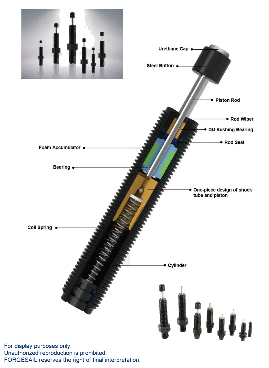
One-Piece Damping Tube and Piston
The damping tube and the piston are machined as a single unit, which is where the capacity advantage comes from. With no joint between the two, the oil column is shorter and the orifice pattern can be placed closer to the point of peak pressure. An internal coil spring returns the rod.
Performance &Advantages
Standard operating range -10 °C to 80 °C, extended to -30 °C to 100 °C with the special seal and hydraulic oil package.
One-piece tube and piston
Over 200 % of the energy absorption of other brands in the same model size.
Matched sealing
Below M20: Japanese NBR rod seal and NBR wiper. From M20 up: polyurethane rod seal and NBR wiper, on a chrome-plated rod.
Side-load bearing
Long front bearing with a bushing, for relaxed alignment tolerance.
0.02 – 5 m/s
Standard impact velocity range, extensible to 20 m/s on request.
-10 °C to 80 °C
Extends to -30 °C to 100 °C with the special seal and oil package.
Three hardness grades
-1 Soft, -2 Middle, -3 Hard — selected by effective weight range.
Model Selection
Select by stroke and energy per cycle, then confirm with the maximum energy per hour. If your duty cycle is demanding, send us the numbers and we will run the calculation for you.

| Model | Stroke (mm) | Max Energy/Cycle (Nm) | Max Energy/Hour (Nm/h) | Cylinder Dia. | Weight (g) |
|---|---|---|---|---|---|
| BC06-04(B) | 4 | 10 | 3,000 | M6×0.75 | 4 |
| BC08-06(B) | 6 | 10 | 8,100 | M8×1.0 | 14 |
| BC10-08(B) | 8 | 10 | 14,800 | M10×1.0 | 21 |
| BC12-10(B) | 10 | 16 | 34,000 | M12×1.0 | 38 |
| BC14-12(B) | 12 | 25 | 41,000 | M14×1.5 | 67 |
| BC14-15(B) | 15 | 35 | 51,200 | M14×1.5 | 74 |
| BC20-15(B) | 15 | 50 | 38,000 | M20×1.5 | 183 |
| BC20-20(B) | 20 | 75 | 55,000 | M20×1.5 | 204 |
| BC20-30(B) | 30 | 95 | 65,000 | M20×1.5 | 226 |
| BC20-50(B) | 50 | 145 | 75,000 | M20×1.5 | 288 |
| BC25-25(B) | 25 | 220 | 111,000 | M25×1.5 | 293 |
| BC25-40(B) | 40 | 270 | 182,000 | M25×1.5 | 343 |
| BC25-50(B) | 50 | 300 | 200,000 | M25×1.5 | 458 |
| BC25-80(B) | 80 | 390 | 210,000 | M25×1.5 | 579 |
| BC36-25(B) | 25 | 330 | 125,000 | M36×1.5 | 760 |
| BC36-50(B) | 50 | 550 | 160,000 | M36×1.5 | 995 |
| BC36-80(B) | 80 | 680 | 230,000 | M36×1.5 | 1,280 |
| No model matches that search. | |||||
Add the hardness suffix to the model number: -1 Soft, -2 Middle, -3 Hard. Suffix (B) = steel strike head.
Choosing the Hardness Grade
- Work out the effective weightInclude the moving mass plus any driven or carried load.
- Confirm the impact velocitySpeed of the body at the moment of contact.
- Select the grade-1 Soft for light loads, -2 Middle for the middle of the range, -3 Hard for the top of the range.
- Send both numbers anywayWe run the calculation and confirm the grade before you order — free, within 48 hours.
BC cannot be retuned after build
This series has no adjustment mechanism. The orifice pattern is fixed at the factory, so the effective weight and impact velocity you give us at enquiry stage drive the selection.
Installation &Maintenance
- Use the buffer as an end stop.
- Remove the steel strike head.
- Exceed the permitted side load angle.
- Paint the piston rod or the body.
- Place it near acids, solvents or soluble cutting oil.
- Expose it to open flame — the unit is oil filled.
- Side load angle must stay below 2°.
- Never use the buffer as an end stop — fit a stop collar 1 mm before end of travel.
- Parallel buffers must be the same model and the same hardness grade.
- Do not paint the piston rod or the body.
- Inspect monthly in frequent service, every 6 months on safety duty.
Send Us Five Numbers — Get a Sizing Report in 48 Hours
Every BC unit is configured against your application data. Give us these five values and our engineers will return a recommended model with verified shock-force versus stroke and deceleration versus stroke curves. Free, and with no commitment to buy.
- W kg · moving weight
- V m/s · impact velocity
- Fp N · driving force
- n pcs · buffers in parallel
- Cycles / hour
BC Series FAQ
Part of a Complete Crane Rail System
Hydraulic buffers are one component we supply. The same engineering and manufacturing team also delivers the rest of the runway system:
- Crane rails — rail sections for crane runway systems
- Rail clips — bolted and welded fastening systems
- Rail pads — vibration and impact damping
- Sole plates — rail support and load distribution
- Rail grouts — cementitious bedding for rail fixings
- Custom machining — molds and precision machined parts
Talk to an Engineer
Tell us your application and we will come back with a recommendation, a sizing calculation and a quotation. If you are still at the design stage, we are happy to work from drawings.

