



BHS Spring-Type Heavy-Duty Buffers — 0.5 to 470 kJ with the Lowest Recoil Force
External mechanical spring return, stroke shorter than bore. Built for low-acceleration braking where any push-back is unacceptable.
What the BHS Series Is For
BHS is the specialist of the range. The stroke is always shorter than the cylinder bore, which makes the unit very stiff and very compact — and the external mechanical spring produces the lowest recoil force of any series we supply.
That combination is what you want on a low-acceleration braking device: somewhere the load has to be brought to rest gently and then left alone, with no residual push from the buffer.
Like the other heavy-duty series, BHS is built to order. We design the orifice pattern around your application data rather than selecting a stock size.
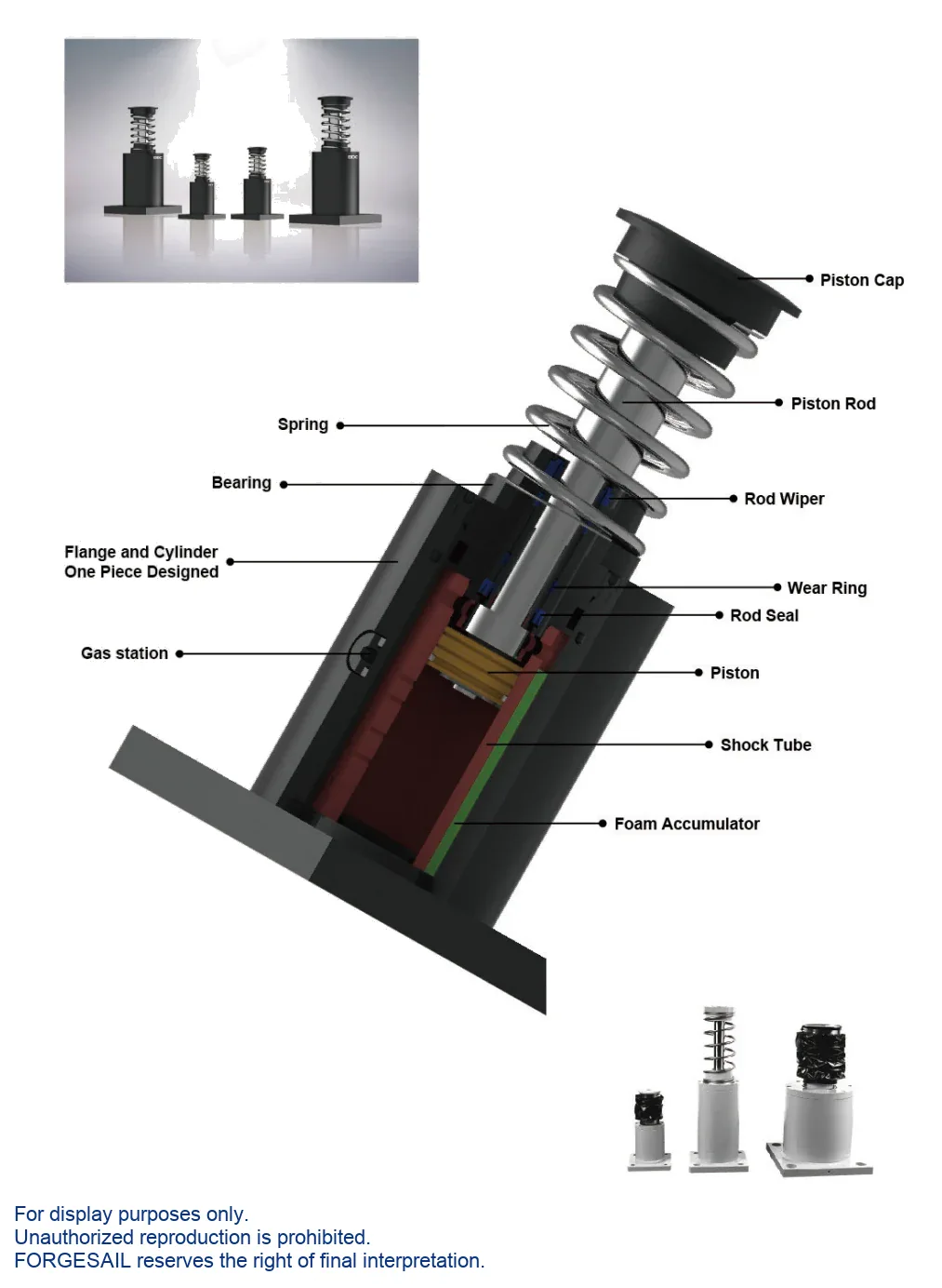
External Mechanical Spring Return
The return spring sits outside the pressure body, so it does not displace oil volume and does not contribute to the damping curve. Compression force is low, which is why recoil is the lowest in the range. Oil is metered through a custom orifice pattern sized to your application.
Performance &Advantages
OSHA / AISE / CMMA / DIN / FEM compliant. Special epoxy-painted cylinder and hard-chrome-plated piston rod for outdoor and corrosive service. 60 cycles/hour maximum.
Lowest recoil force
An external spring compresses more gently than any internal return mechanism.
Custom orifice pattern
Designed around your application data for maximum energy absorption.
Widest bore range
Ø64 to Ø360 — the largest cylinder diameter in the range.
Certified design
Meets OSHA, AISE, CMMA, DIN and FEM requirements.
Outdoor and corrosive duty
Special epoxy paint system and hard-chrome-plated piston rod as standard.
-35 °C to 100 °C
With the special seal and hydraulic oil package, up from -10 °C to 60 °C.
Model Selection
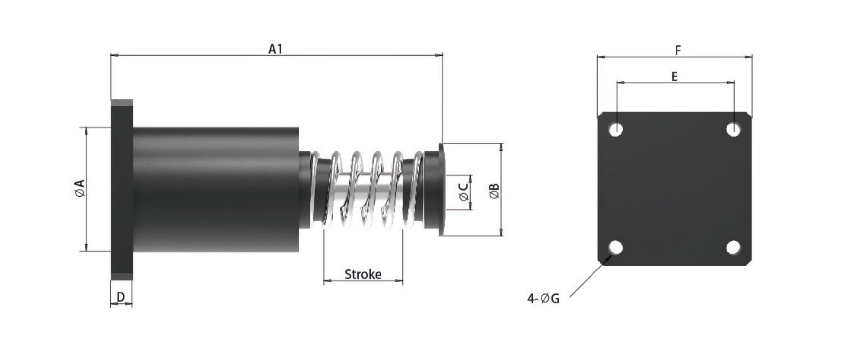
Select by stroke and energy per cycle, then confirm with the maximum energy per hour. If your duty cycle is demanding, send us the numbers and we will run the calculation for you.
| Model Group | Stroke Range (mm) | Max Energy/Cycle (kJ) | Cylinder Ø (mm) |
|---|---|---|---|
| BHS64 | 50 | 0.5 | Ø64 |
| BHS90 | 50 – 100 | 4 – 8 | Ø90 |
| BHS100 | 50 – 100 | 4.4 – 8.8 | Ø100 |
| BHS130 | 70 – 150 | 10 – 21 | Ø130 |
| BHS170 | 80 – 150 | 24 – 45 | Ø170 |
| BHS190 | 100 – 150 | 40 – 60 | Ø190 |
| BHS220 | 100 – 150 | 44 – 66 | Ø220 |
| BHS250 | 100 – 150 | 60 – 180 | Ø250 |
| BHS300 | 150 – 250 | 117 – 180 | Ø300 |
| BHS340 | 200 – 300 | 200 – 300 | Ø340 |
| BHS360 | 250 – 400 | 294 – 470 | Ø360 |
| No model matches that search. | |||
Model group shown as BHS <bore >×<stroke >— for example BHS130×150. Rear flange (FR) is the standard mounting arrangement; other arrangements are built to order.
Mounting Arrangements &Accessories
Rear flange is the standard arrangement
BHS ships with a rear flange (FR) as standard. Front flange, double flange, foot mount and clevis arrangements can be built to order — please specify at enquiry stage.
Accessories
Installation &Maintenance
- Use the buffer as an end stop.
- Remove the steel strike head.
- Exceed the permitted side load angle.
- Paint the piston rod or the body.
- Place it near acids, solvents or soluble cutting oil.
- Expose it to open flame — the unit is oil filled.
- Rear flange (FR) is the standard mounting. Other arrangements must be specified at enquiry stage.
- Side load angle: below 2.5° at strokes up to 300 mm, below 1° above 300 mm.
- Never use the buffer as an end stop — fit a stop collar 1 mm before end of travel.
- Keep the external spring free of paint, dirt and corrosion deposits.
- Inspect every 6 months on safety and emergency duty, monthly in frequent service.
Send Us Five Numbers — Get a Sizing Report in 48 Hours
Every BHS unit is configured against your application data. Give us these five values and our engineers will return a recommended model with verified shock-force versus stroke and deceleration versus stroke curves. Free, and with no commitment to buy.
- W kg · moving weight
- V m/s · impact velocity
- Fp N · driving force
- n pcs · buffers in parallel
- Cycles / hour
BHS Series FAQ
Part of a Complete Crane Rail System
Hydraulic buffers are one component we supply. The same engineering and manufacturing team also delivers the rest of the runway system:
- Crane rails — rail sections for crane runway systems
- Rail clips — bolted and welded fastening systems
- Rail pads — vibration and impact damping
- Sole plates — rail support and load distribution
- Rail grouts — cementitious bedding for rail fixings
- Custom machining — molds and precision machined parts
Talk to an Engineer
Tell us your application and we will come back with a recommendation, a sizing calculation and a quotation. If you are still at the design stage, we are happy to work from drawings.

