


Introduction: The Blank Decides Everything
A crane rail sole plate looks like a plain steel rectangle. In service it is a precision component that sets the rail seat, carries the clip load and spreads wheel pressure into the foundation.
Every one of those duties is decided by the blank. If the plate is not flat, not square or not drilled in the right place, no amount of care later in the workshop will fix it.
That is why laser cutting steel plates for crane rail sole plates is a manufacturing decision, not just a cutting choice. This guide covers the 7 facts that matter.

The 7 Facts at a Glance
- 1. A crane rail sole plate sets both the rail seat height and the clip preload.
- 2. Flatness matters more than absolute thickness. A plate that rocks loses clip force.
- 3. Hole position controls fit-up. A one-millimetre error can stop a clip from seating.
- 4. Fiber laser cutting holds tighter edge and hole tolerances than plasma or oxy-fuel on thin and medium plate.
- 5. Burrs must be removed. They hold the plate off the grout and create point loading.
- 6. Gauge is set by the pair of sole plates on both rails, not by one plate alone.
- 7. Inspect flatness, hole position, edge squareness and burr height before dispatch.
Note: tolerances quoted in this article are typical industry values. The project specification and the fastening system supplier’s requirements always govern.

1. What a Crane Rail Sole Plate Actually Does
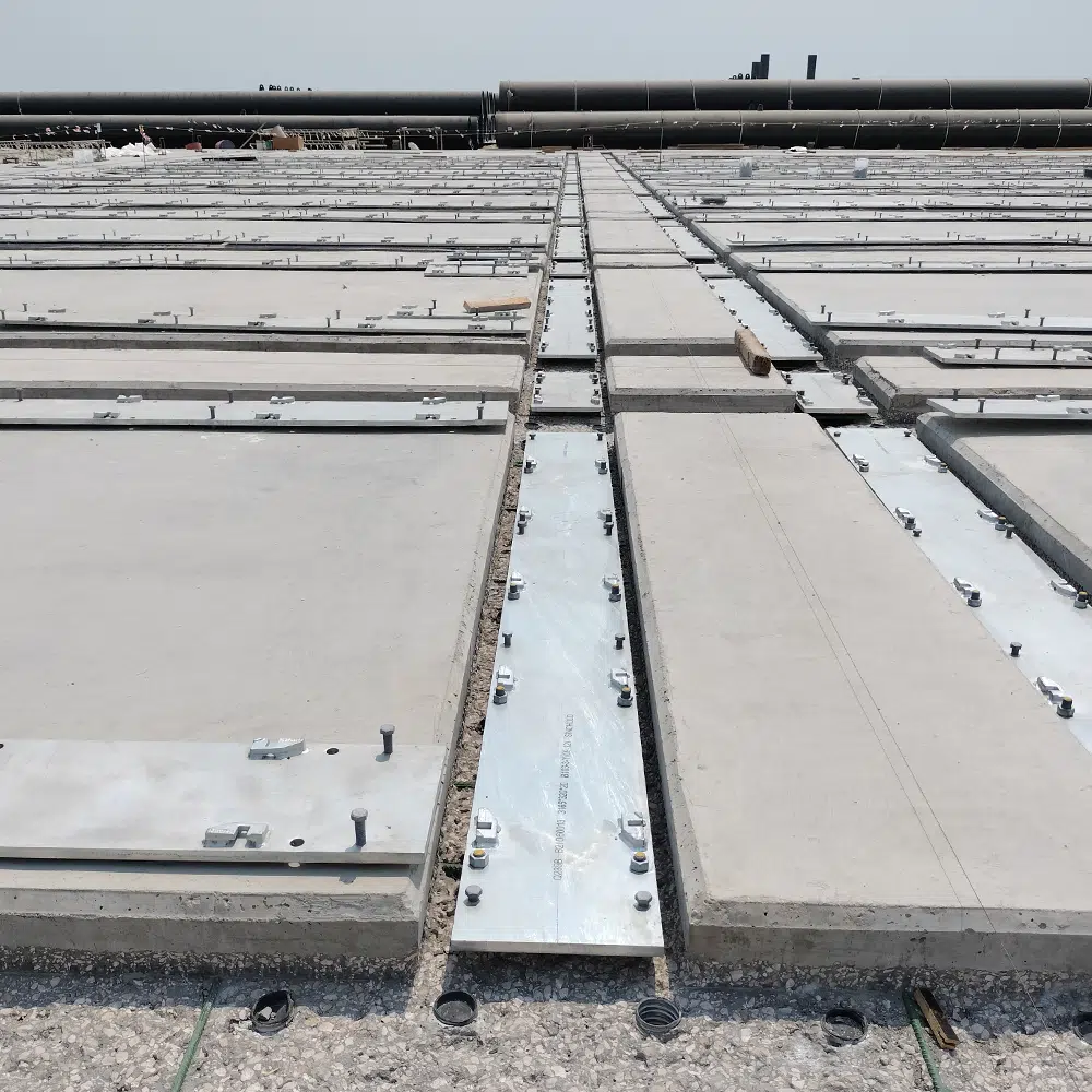
The sole plate sits between the rail base and the foundation. It provides a flat, stable seat, and it gives the rail clip something solid to react against.
It also sets the rail seat height. Get that wrong across a runway and the two rails sit at different levels, which tilts the crane bridge under load.
The load path is simple: wheel, rail, rail pad, sole plate, grout, foundation. Any gap or high spot in that chain shows up as movement.
For the forces involved, see our crane rail force analysis.
2. Flatness: The Crane Rail Sole Plate Tolerance That Decides Clip Life
Flatness is the tolerance most often underestimated. A sole plate with a bowed or twisted top surface lets the rail rock under every wheel pass.
When the rail rocks, the clip has to absorb movement it was never designed for. Toe load drops, the clip fatigues, and the rail starts to creep.
Project specifications commonly call for flatness within a few tenths of a millimetre over a 300 mm straightedge. Confirm the exact figure with your fastening supplier.
Flatness also affects the grout layer. A warped plate produces an uneven grout thickness, which is covered in our rail foundation grouting guide.
3. Hole Position Accuracy on the Crane Rail Sole Plate
Every crane rail sole plate carries holes for anchor bolts, clip fixings or both. Their position decides whether the assembly goes together on site.
A clip system has limited lateral adjustment. Once the hole is outside that window, the clip cannot be fitted and the plate has to be reworked or scrapped.
Hole position tolerance is typically tighter than the plate outline tolerance. Where a hole is used for locating rather than clearance, the tolerance tightens further.
4. Edge Quality, Burrs and Coating After Laser Cutting
Laser cutting produces a narrow kerf and a small heat-affected zone, which keeps the plate edge square and dimensionally stable.
Burrs are the practical issue. A burr under the plate holds it off the grout and creates point loading. A burr on a hole face stops the clip or bolt washer from seating flush.
Deburring is therefore part of the manufacturing sequence, not an optional finishing step.
5. Choosing the Cutting Process for Crane Rail Sole Plate Production
Sole plates can be cut by plasma, oxy-fuel, waterjet or laser. Each has a different accuracy and edge-quality profile.
For blank cutting we use DXTECH fiber laser cutting machines, which hold tight tolerances on plate edges and hole positions.
Compared with plasma and oxy-fuel, fiber laser cutting gives a narrower kerf, less dross and a smaller heat-affected zone, so less secondary machining is needed.
For very thick plate, confirm the achievable tolerance with the machine supplier, because cutting quality falls as thickness rises.
6. Gauge Control Across the Runway
Gauge is the distance between the two rail centrelines, and it is set by the pair of sole plates, not by one plate on its own.
If each plate is accurate but the pair is not matched, the crane wheels will bind or track off-centre. Our guide to crane rail alignment tolerance covers the field measurement side.
This is why sole plates for a runway should be cut, marked and shipped as a matched set.
7. Inspection Checklist Before Dispatch
A short inspection before dispatch prevents expensive site rework. Measure these four items on every batch:
- Flatness across the rail seat, over the specified straightedge length.
- Hole position and hole diameter, checked against the clip supplier’s drawing.
- Edge squareness and burr height on cut edges and hole faces.
- Plate thickness at several points, to confirm the mill tolerance is acceptable.
Record the results by plate and by runway side, so any site query can be traced back to the batch.

Conclusion
Crane rail sole plate accuracy is decided at the blank. Flatness, hole position, edge quality and gauge control all start with how the plate was cut.
Laser cutting steel plates gives the repeatability that heavy-duty crane runways need, and it reduces secondary machining after cutting.
ForgeSail supplies crane rails, rail clips, rail pads and machined sole plates for ports, mines and heavy industry. Contact our engineering team to review your drawings and tolerances.
References
- EN 1090-2 — Execution of steel structures and aluminium structures — Part 2: Technical requirements for steel structures
- EN 10025-2 — Hot rolled products of structural steels — Part 2: Technical delivery conditions for non-alloy structural steels
- ISO 9013 — Thermal cutting — Classification of thermal cuts — Geometrical product specification and quality tolerances
- Project drawings and the fastening system supplier’s installation manual take precedence over general guidance.