



BHD Air-Bag Heavy-Duty Hydraulic Buffers — Up to 900 kJ per Cycle, 1500 mm Stroke
The reference solution for AS/RS stacker cranes and overhead cranes. A nitrogen bladder returns the rod with almost no recoil, so the buffer stops your load without pushing it back.
What the BHD Series Is For
BHD is the flagship of the range and the series we recommend most often to Forgesail customers. It carries the highest energy per cycle and the longest stroke of any series we supply, and it does it with a nitrogen air bag instead of a mechanical return spring.
That air bag is the whole point. It makes the body shorter for a given stroke, lowers the peak damping force, and — critically — produces a very small recoil force. On a stacker crane running a high-bay aisle, that means the buffer stops the carriage without shoving it back down the track.
Every unit is built to order. We design the orifice pattern around your application data rather than pulling a size off a catalogue page, which is what allows the series to reach 900 kJ per cycle and 1500 mm of stroke.
The series is validated across the full speed range of modern stacker cranes — 60, 90, 120, 150, 180 and 210 m/min — in a six-speed test programme carried out for Dematic.
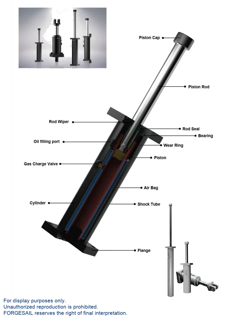
Nitrogen Air-Bag Return
Oil displaced during compression squeezes a sealed nitrogen bladder. On the return stroke the bladder expands and pushes the oil back, resetting the piston rod. Because the restoring force comes from gas compression rather than a steel spring, the recoil is gentle and the body stays short — two things that matter enormously on a crane or a stacker.
Performance &Advantages
OSHA / AISE / CMMA / DIN / FEM compliant. Special epoxy-painted cylinder and hard-chrome-plated piston rod for outdoor and corrosive service. 60 cycles/hour maximum.
Up to 900 kJ per cycle
Compact, long-stroke construction with smooth deceleration over the full stroke.
Built around your data
We design the orifice pattern for your application rather than selling a stock size.
Certified design
Meets OSHA, AISE, CMMA, DIN and FEM requirements.
60 cycles per hour
Maximum cycle rate, at impact velocities up to 6 m/s.
Almost no recoil
The nitrogen bladder returns the rod without pushing the load back.
Outdoor and corrosive duty
Special epoxy paint system and hard-chrome-plated piston rod as standard.
Accessory range
Piston rod bellow, U-clamp, safety chain and rod-return position sensor.
-35 °C to 100 °C
With the special seal and hydraulic oil package, up from -10 °C to 60 °C.
Custom design service
Our engineers will size and configure the unit against your drawings.
Model Selection
Select by stroke and energy per cycle, then confirm with the maximum energy per hour. If your duty cycle is demanding, send us the numbers and we will run the calculation for you.

| Model Group | Stroke Range (mm) | Max Energy/Cycle (Nm) | Cylinder Ø (mm) | Bolt Spec |
|---|---|---|---|---|
| BHD1.5 | 50 – 800 | 3,200 – 36,500 | Ø90 | M12 |
| BHD2.0 | 150 – 1400 | 14,400 – 104,200 | Ø110 | M16 |
| BHD3.0 | 50 – 1500 | 9,600 – 206,800 | Ø130 | M20 |
| BHD3.5 | 50 – 1200 | 13,000 – 204,000 | Ø155 | M20 |
| BHD4.0 | 50 – 1200 | 15,100 – 329,300 | Ø200 | M24 |
| BHD5.0 | 100 – 1200 | 46,700 – 535,800 | Ø215 | M30 |
| BHD6.0 | 100 – 1200 | 76,500 – 898,200 | Ø275 | M36 |
| No model matches that search. | ||||
Model group shown as BHD <bore >×<stroke >— for example BHD3.0×2 for a Ø130 body with a 2 inch stroke code. Add the mounting code (FF / FR / TF / FM / CM) and options (SC / SS / PB). Energy figures are taken from the detailed pages of the BDC catalogue; final values are confirmed against your application data at enquiry stage.
Mounting Arrangements &Accessories
Five standard mounting arrangements. Add SC for a safety chain, SS for a rod-return position sensor, or PB for a piston rod bellow.
Accessories
Installation &Maintenance
- Use the buffer as an end stop.
- Remove the steel strike head.
- Exceed the permitted side load angle.
- Paint the piston rod or the body.
- Place it near acids, solvents or soluble cutting oil.
- Expose it to open flame — the unit is oil filled.
- Side load angle: below 2.5° at strokes up to 300 mm, below 1° above 300 mm.
- Never use the buffer as an end stop — fit a stop collar 1 mm before end of travel.
- Fit a safety chain on any installation above 2 m height.
- Check the rod returns to its full catalogued length. If it does not, the air bag needs recharging.
- Inspect every 6 months on safety and emergency duty, monthly in frequent service.
Send Us Five Numbers — Get a Sizing Report in 48 Hours
Every BHD unit is configured against your application data. Give us these five values and our engineers will return a recommended model with verified shock-force versus stroke and deceleration versus stroke curves. Free, and with no commitment to buy.
- W kg · moving weight
- V m/s · impact velocity
- Fp N · driving force
- n pcs · buffers in parallel
- Cycles / hour
BHD Series FAQ
Part of a Complete Crane Rail System
Hydraulic buffers are one component we supply. The same engineering and manufacturing team also delivers the rest of the runway system:
- Crane rails — rail sections for crane runway systems
- Rail clips — bolted and welded fastening systems
- Rail pads — vibration and impact damping
- Sole plates — rail support and load distribution
- Rail grouts — cementitious bedding for rail fixings
- Custom machining — molds and precision machined parts
Talk to an Engineer
Tell us your application and we will come back with a recommendation, a sizing calculation and a quotation. If you are still at the design stage, we are happy to work from drawings.

