



BHI Series

BHI Hydraulic-Pneumatic Buffers — Twice the Energy in the Same Bore, 4 to 720 kJ

Landing-gear derived technology. Oil and nitrogen absorb the impact together, giving more than double the energy of other structures in the same cylinder diameter and stroke.

4 – 720 kJEnergy per cycle
50 – 1000 mmStroke range
Ø65 – Ø180Cylinder bore
2×Energy vs. other structures
3 – 10 barNitrogen pressure
Overview

What the BHI Series Is For

BHI came out of aircraft landing gear, and it still behaves like it. Hydraulic oil and nitrogen gas absorb the impact energy together: the oil handles the damping, while a nitrogen chamber stores part of the energy as potential energy and drives the return stroke.

The result is more than twice the energy absorption of other structures at the same cylinder diameter and stroke, plus a return force far larger than any other series. That combination is exactly what an end-of-track stop or a port crane emergency brake needs — high energy in a tight space, and a positive return afterwards.

Alongside port machinery, railway end-of-track stops are the second reference application for this series. Both are designed to meet OSHA, AISE, CMMA, DIN and FEM requirements.
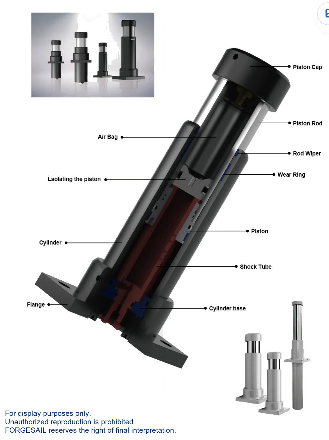
BHI Hydraulic-Pneumatic Heavy-Duty Buffers — exploded view of internal components
>
Energy Absorption

Hydraulic-Pneumatic Synergy

An isolating piston separates the oil column from the nitrogen chamber. On impact, oil is metered through the orifice stack while the nitrogen compresses — so part of the kinetic energy is dissipated as heat and part is stored as gas pressure. The stored energy then drives the return stroke, which is why BHI has the strongest recoil of any series.

N ₂impactpistonisolatingnitrogen
Figure. Hydraulic-Pneumatic Synergy — schematic cross-section, not to scale. Dimensional drawings and 3D STEP files are supplied with every quotation.
Performance

Performance &Advantages

OSHA / AISE / CMMA / DIN / FEM compliant. Special epoxy-painted cylinder and hard-chrome-plated piston rod for outdoor and corrosive service. 60 cycles/hour maximum.

01

Compact, high energy

More than twice the absorption of other structures in the same bore and stroke.

02

Built around your data

Custom orifice pattern designed for your application.

03

Certified design

Meets OSHA, AISE, CMMA, DIN and FEM requirements.

04

Strong return force

The nitrogen chamber drives the rod back harder than any other series — ideal for rail end stops.

05

Emergency braking

The reference choice for port machinery and railway end-of-track stops.

06

Outdoor and corrosive duty

Special epoxy paint system and hard-chrome-plated piston rod as standard.

07

Accessory range

Piston rod bellow and safety chain available.

08

-35 °C to 100 °C

With the special seal and hydraulic oil package, up from -10 °C to 60 °C.

09

Custom design service

Our engineers will size and configure the unit against your drawings.

Model Selection

Model Selection

Select by stroke and energy per cycle, then confirm with the maximum energy per hour. If your duty cycle is demanding, send us the numbers and we will run the calculation for you.
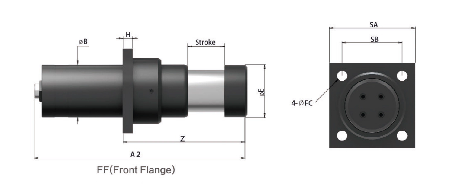
BHI Hydraulic-Pneumatic Heavy-Duty Buffers — engineering data: dimensions, stroke and energy ratings
Model GroupStroke Range (mm)Max Energy/Cycle (kJ)Cylinder Ø (mm)
BHI6550 – 1004 – 8Ø65
BHI8550 – 1008 – 16Ø85
BHI10050 – 80010 – 132Ø100
BHI120100 – 100032 – 260Ø120
BHI130250 – 800100 – 270Ø130
BHI150115 – 100062 – 510 Ø150
BHI180100 – 100080 – 720Ø180
No model matches that search.
← Swipe to see all columns →

Model group shown as BHI <bore >×<stroke >— for example BHI120×200. Add the mounting code (FF / FR) and options (SC / PB).

Mounting

Mounting Arrangements &Accessories

Front flange (FF) and rear flange (FR) are the standard arrangements for this series. Add a safety chain on any installation above 2 m height.

FFFront Flange
FRRear Flange
TFFront + Rear
FMFoot Mount
CMU Clevis

Accessories

SCSafety chain — mandatory on any installation above 2 m height.
PBPiston rod bellow — strongly recommended in dusty service.
Installation &Maintenance

Installation &Maintenance

Never do this
  • Use the buffer as an end stop.
  • Remove the steel strike head.
  • Exceed the permitted side load angle.
  • Paint the piston rod or the body.
  • Place it near acids, solvents or soluble cutting oil.
  • Expose it to open flame — the unit is oil filled.
Do this
  • Keep the nitrogen chamber between 3 and 10 bar. Standard factory setting is 5 bar.
  • Check and top up through the gas filling nozzle under the bolt at the top of the piston rod.
  • Use nitrogen. If another gas is used it must be free of salt and moisture.
  • Close the knob by turning right; loosen by turning left.
  • Charging sequence: set the cylinder to 3–5 bar, fit the tyre-type nozzle, turn the knob right to close, then remove the nozzle and refit the cap.
  • Inspect every 6 months on safety and emergency duty, monthly in frequent service.
What We Need From You

Send Us Five Numbers — Get a Sizing Report in 48 Hours

Every BHI unit is configured against your application data. Give us these five values and our engineers will return a recommended model with verified shock-force versus stroke and deceleration versus stroke curves. Free, and with no commitment to buy.

  • W kg · moving weight
  • V m/s · impact velocity
  • Fp N · driving force
  • n pcs · buffers in parallel
  • Cycles / hour
FAQ

BHI Series FAQ

Both are heavy‑duty buffers, but they return the piston rod differently. BHD uses a nitrogen air bag and has a very small recoil force — best for stacker cranes and overhead cranes where you do not want the load pushed back. BHI uses oil and nitrogen together, absorbs more than twice the energy in the same cylinder diameter and stroke, and has a much larger return force — best for railway end stops and emergency braking where space is tight and a positive return is needed.
Between 3 and 10 bar, with 5 bar as the standard factory setting. The pressure is checked and topped up through the gas filling nozzle under the bolt at the top of the piston rod, using any standard tyre‑type nozzle aerator. Use nitrogen, and if you use another gas make sure it is free of salt and moisture.
Yes — this is one of its two reference applications, alongside port machinery. The combination of high energy absorption in a compact body and a strong piston rod return force is exactly what an end‑of‑track stop requires, and the series is designed to meet OSHA, AISE, CMMA, DIN and FEM requirements.
Front flange (FF) and rear flange (FR) as standard. Piston rod bellow (PB) and safety chain (SC) are available as options; we specify the safety chain on any installation above 2 m height.
Yes. Cylinders are special epoxy painted and piston rods are hard‑chrome plated for outdoor and corrosive service. With the optional seal and oil package the operating range extends from the standard ‑10 °C to 60 °C up to ‑35 °C to 100 °C.

Talk to an Engineer

Tell us your application and we will come back with a recommendation, a sizing calculation and a quotation. If you are still at the design stage, we are happy to work from drawings.

滚动至顶部
ENFRESRU