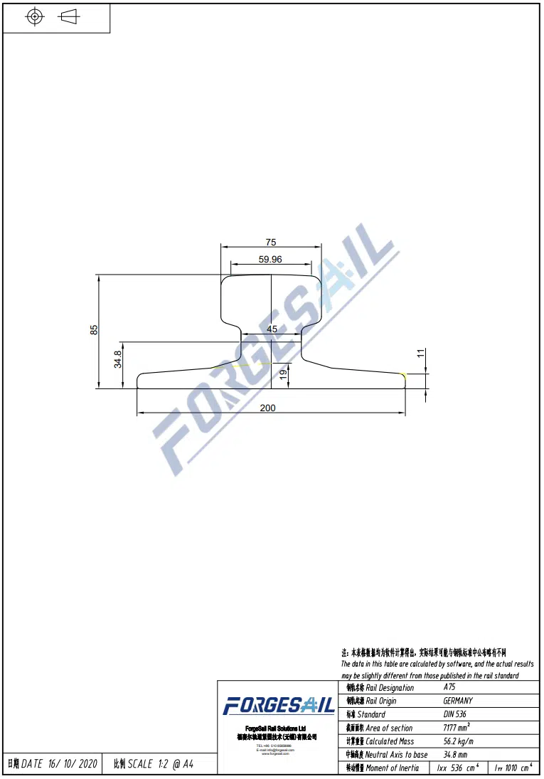



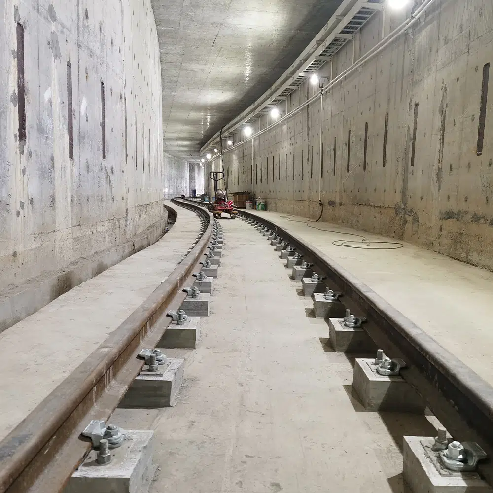
A few millimetres can make the difference between a crane that runs smoothly for 20 years and one that chews through wheels, shakes its structure apart, and risks derailment every shift.
Understanding crane rail. See our complete crane rail specifications alignment tolerance is not optional — it is a fundamental requirement for safe overhead crane operation. Misaligned rails cause accelerated wheel wear, structural fatigue, and unplanned downtime that costs far more than the initial alignment work.
This guide explains the 5 critical crane rail alignment tolerance parameters defined by ISO 12488-1, BS 466, and FEM 1.001 — the three most widely used international standards for crane runway installation.

Why Crane Rail Alignment Tolerance Matters
Before diving into numbers, it helps to understand the consequences of poor alignment.
A typical 20-tonne overhead crane running on a 20-metre span exerts significant lateral forces at the wheel-rail interface. When the crane rail alignment tolerance is exceeded by even 3–5 mm at a single joint, the wheel flange contacts the rail head every time the crane passes. Over 500 cycles per day, that contact generates:
– Localised rail head wear — up to 5× faster than normal
– Wheel flange thinning — requiring replacement 3× sooner
– Increased drive motor current — higher energy consumption
– Structural fatigue — cracked runway beams and loose bolts
The cost of a single prolonged shutdown at a port or steel mill often exceeds the entire cost of a professional rail alignment survey.

The 5 Critical Crane Rail Alignment Tolerance Parameters
1. Span (Gauge) Tolerance
The span is the horizontal distance between the centre lines of the two rail heads. It must match the crane’s design wheelbase.
| Standard | Span Range | Tolerance |
| **BS 466** | S ≤ 12 m | ±3 mm |
| **BS 466** | S > 12 m | ±[3 + 0.25 × (S − 12)] mm |
| **ISO 12488-1 / FEM 1.001** | S ≤ 16 m | ±5 mm |
| **ISO 12488-1 / FEM 1.001** | S > 16 m | ±[5 + 0.25 × (S − 16)] mm |
| **CMAA Spec 74 (US)** | All spans | ±6 mm (±1/4 inch) |
Example: For a 20-metre span crane:
– BS 466: ±[3 + 0.25 × (20 − 12)] = ±5 mm
– ISO 12488: ±[5 + 0.25 × (20 − 16)] = ±6 mm
The tolerance is measured at any point along the runway. If the rails bow inward or outward beyond these limits, the crane’s wheels will bind or drop off the edge.
2. Horizontal Straightness (Left/Right Alignment)
Each rail must be straight in the horizontal plane. Two measurements are required:
– Local tolerance: ≤ 1 mm per 1 metre of rail length
– Total bay length: ≤ 10 mm from the reference datum line
The local tolerance (≤ 1 mm/m) is the stricter of the two. A sharp kink of 3 mm over a 2-metre section, for example, would fail even if the total bay deviation is under 10 mm.
This is the most commonly violated crane rail alignment tolerance parameter in older installations, particularly at welded rail joints where post-weld straightening was inadequate.

3. Vertical Alignment (Elevation Tolerance)
Both rails must sit at the same elevation. The crane rail alignment tolerance for vertical deviation is:
– Maximum elevation difference between rails: ≤ 10 mm total
– Maximum deviation rate: ≤ 1 mm per 1 metre of span (BS 466: 0.001 × span)
Example: For a 15-metre span:
– BS 466 formula: 0.001 × 15,000 mm = 15 mm, but capped at 10 mm absolute maximum
A difference in elevation of even 5 mm causes the crane bridge to twist under load, transferring lateral forces to the rail flanges and increasing wear on the entire drive train.
4. Rail End Step (Vertical Offset at Joints)
At every rail joint where two rail sections meet, the vertical step between them must be minimised.
– Maximum vertical step (industry standard): ≤ 1 mm
– Maximum horizontal offset at joint: ≤ 1 mm
Any step larger than 1 mm creates an impact load every time the crane wheel crosses. Over 500 crossings per day, this generates dynamic forces that can exceed the static design load by 2–3 times.
If the step exceeds 1 mm, the rail ends must be ground smooth or, ideally, welded together to create a continuous running surface.
5. Rail End Gap
Thermal expansion requires a controlled gap between rail ends (unless the rails are continuous welded rail / CWR).
– Standard expansion gap: 3–8 mm depending on installation temperature
– Gap at reference temperature (20°C): approximately 5 mm
The gap must be positioned correctly. If the gap is too narrow, the rails will buckle in summer heat. If too wide, the crane wheel will impact the trailing rail end, causing accelerated battering at every joint.
International Standards Comparison
Different regions follow different codes. Here is how the major crane rail alignment tolerance standards compare:
| Parameter | BS 466 (UK/Commonwealth) | ISO 12488-1 (International) | FEM 1.001 (Europe) | CMAA 74 (USA) |
| Span tolerance | ±3 mm (S≤12m) | ±5 mm (S≤16m) | Same as ISO | ±6 mm |
| Local straightness | ≤1 mm/m | ≤1 mm/m | ≤1 mm/m | ≤1/8 inch/10ft (≈1 mm/m) |
| Elevation (total) | ≤10 mm | ≤10 mm | ≤10 mm | ≤3/8 inch (≈10 mm) |
| Rail step at joint | ≤1 mm | ≤1 mm | ≤1 mm | ≤1/32 inch (≈0.8 mm) |
| Rail end gap | 3–8 mm | 3–8 mm | 3–8 mm | Per thermal calculation |
For global projects, ISO 12488-1:2012 is the recommended reference standard. Most national codes align closely with its values.
How to Measure Crane Rail Alignment Tolerance
Alignment measurements only make sense once the supporting structure is known to be in acceptable condition. On existing runways, a crane runway survey should be carried out before alignment work begins, covering runway geometry, rail-to-runway interfaces, and building clearances that may limit correction options. Findings from that survey determine whether the rail can simply be re-aligned or whether the runway itself needs repair or reinforcement.
Professional measurement requires:
1. Total station or laser tracker — for overall bay alignment
2. Precision spirit level and optical level — for elevation checks
3. Dial gauge and straight edge (1 m or 2 m) — for local straightness at joints
4. Steel tape (calibrated) or EDM — for span measurement
5. Rail profile gauge — for rail head wear assessment
For best results, measurements should be taken:
– Before installation — verify the runway beam
– After rail installation — confirm all tolerances before crane commissioning
– Annually — monitor creep and settlement
– After any significant structural modification — regrouting, beam replacement
Consequences of Exceeding Crane Rail Alignment Tolerance
When any of the 5 parameters exceeds the tolerance limits, the consequences cascade from accelerated wear to structural failure. The table below summarizes how each alignment fault affects crane operation in the short and long term.
| Fault | Immediate Effect | Long-Term Damage |
| Span too wide | Wheel flange rides rail edge | Derailment risk, wheel flange fracture |
| Span too narrow | Wheel flange binds on rail web | Gauge face wear, rail overturning |
| Elevation difference | Crane leans under load | Bridge twist, unequal wheel loading |
| Rail step >1 mm | Impact loading at each pass | Rail head battering, cracked fishplates |
| Horizontal kink | Wheel snaking, lateral oscillation | Loose rail clips, beam fatigue |
| Inadequate expansion gap | Thermal buckling in summer | Rail distortion, weld fracture |
Best Practices for Meeting Crane Rail Alignment Tolerance
1. Specify the standard in your procurement contract — Do not leave alignment tolerances to chance. Reference ISO 12488-1 or BS 466 explicitly.
2. Use adjustable rail clips — Forged clips with shim adjustment allow fine correction after installation.
3. Weld rail joints (CWR) — Eliminates the step and gap issues at joints entirely.
4. Grout the rail firmly — Full-contact grouting under the rail base prevents settlement and movement.
5. Install expansion joints correctly — Position them at beam ends, calculate gaps based on local temperature range.
6. Conduct a final alignment survey — Before handing over to the client, measure and document every parameter.

Conclusion
Crane rail alignment tolerance is not just a specification on paper — it is the foundation of safe, reliable crane operation. The 5 critical parameters — span, horizontal straightness, vertical elevation, rail end step, and expansion gap — are defined by international standards including ISO 12488-1, BS 466, FEM 1.001, and CMAA 74. Each standard uses slightly different values, but all agree on the key principle: precision matters.
For crane rails in ports, mines, steel plants, and heavy industry, ForgeSail supplies certified crane rail systems with full alignment support. Contact our engineering team to discuss your crane rail alignment tolerance requirements.
References
- ISO 12488-1:2012 — Cranes — Tolerances for wheels and travel and crane tracks
- BS 466:1984 — Specification for power-driven overhead travelling cranes
- FEM 1.001 — Rules for the design of hoisting appliances
- CMAA Specification 74 — For overhead and gantry cranes
- DNVGL-ST-0378:2023 — Standard for ship-to-shore container cranes (port crane rail guidelines)