


Understanding Rail Clip Failure in Crane Rail Systems
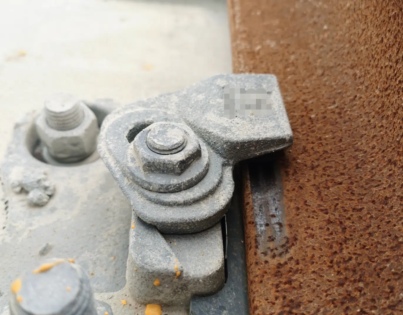
Rail clips are the primary fastening component in any crane rail system. They secure the rail to the supporting beam, resist lateral forces from crane movement, and maintain consistent clamping force under dynamic loading. When a rail clip fails, the consequences range from accelerated rail wear to catastrophic derailment and costly production downtime.
Understanding the mechanisms behind rail clip failure is essential for maintenance engineers, project managers, and procurement professionals who specify fastening systems for ports, steel mills, shipyards, and industrial facilities. This guide examines the five most common rail clip failure modes and presents proven prevention strategies.
The five failure modes covered in this guide are:
- 1. Lateral displacement (side-shift) caused by inadequate clamping force
- 2. Clip fracture and breakage due to casting porosity or material fatigue
- 3. Rail pad deterioration leading to clamping force loss
- 4. Corrosion and environmental degradation of clip and bolt assemblies
- 5. Improper installation and torque relaxation over time

Failure Mode 1: Lateral Displacement — A Common Rail Clip Failure
Lateral displacement occurs when the rail clip cannot maintain sufficient clamping force to hold the rail in position against the horizontal forces generated by crane acceleration, braking, and wheel flange contact. In severe cases, the clip nose loses contact with the rail base, allowing the rail to shift laterally by several millimeters per cycle.

Root Causes
Several factors contribute to lateral displacement:
- Rubber nose compression set: Repeated loading causes the rubber pad on the clip nose to take a permanent set, reducing clamping force over time.
- Inadequate clamping torque: Bolts not torqued to specification, or torque loss due to vibration and thermal cycling.
- Recycled rubber content: Low-grade rubber compounds may contain recycled material that loses elasticity faster, accelerating force loss.
- Incorrect clip geometry: The contact angle between clip nose and rail base must match the specific rail profile. A mismatch concentrates stress and reduces effective clamping.
Prevention Strategy
ForgeSail addresses lateral displacement through two key design choices. First, the rubber nose is manufactured from virgin EPDM (ethylene propylene diene monomer) rubber — not recycled material — vulcanized directly to the steel clip body. Virgin EPDM suits outdoor coastal applications due to its UV and ozone resistance; NBR vulcanized pads are recommended for steel mills with heavy oil contamination. Virgin EPDM provides significantly better compression set resistance, ozone resistance, and service life compared to compounds containing recycled rubber.
Second, the clip nose incorporates an integrated raised boss (凸起设计) at the contact interface. This geometric feature creates a mechanical interlock between the clip nose and the rail base edge, providing redundant retention even if rubber compression set occurs over extended service. The result is a fastening system that maintains lateral restraint 3–5× longer than designs relying solely on rubber compression force.
ForgeSail’s welded and bolted rail clip systems incorporate these features as standard.

Failure Mode 2: Clip Fracture — How Manufacturing Quality Prevents Rail Clip Failure
Fracture is the most dangerous rail clip failure mode. A broken clip releases the rail completely at that point, creating a localized stress concentration that can cascade to adjacent clips and cause catastrophic track failure.

Root Causes: Casting vs Forging
The manufacturing process has a direct impact on fracture resistance. Many rail clips on the market are manufactured through sand casting, which introduces inherent microstructural weaknesses:
| Property | Cast Clip (Sand Casting) | Forged Clip (Hot Forging) |
| Internal porosity | Common — shrinkage voids and gas pockets weaken section | Near-zero — forging closes internal voids |
| Grain structure | Random, non-directional | Aligned grain flow follows clip contour |
| Typical material | ZG 270–500 (cast steel, ~270 MPa yield) | Q355B (forged steel, ≥355 MPa yield) |
| Fatigue life | Lower — porosity initiates micro-cracks | Higher — continuous grain flow resists crack propagation |
| Consistency | Variable — depends on casting quality | Consistent — controlled forging process |
| Visual inspection | Surface may hide internal defects | Dye-penetrant / magnetic particle testing is reliable |
Note: Cast rail clips are acceptable for light-duty indoor crane tracks with annual tonnage below 500,000 tons, though fatigue service life is significantly shorter than forged alternatives.
Sand casting produces clips with random grain orientation and internal porosity — microscopic voids formed during solidification. Under cyclic loading, these voids act as crack initiation sites. The crack propagates along grain boundaries until catastrophic fracture occurs.
In contrast, hot forging (at approximately 1,200 °C) aligns the steel’s grain structure along the clip contour, eliminating internal voids and producing a continuous grain flow that follows the part geometry. This results in a clip with significantly higher fatigue resistance and consistent mechanical properties batch to batch.
Prevention Strategy
ForgeSail manufactures all heavy-duty rail clips using hot-forged Q355B steel (≈ EN 10025 S355JR / ASTM A572 Grade 50, minimum yield strength 355 MPa) rather than sand casting. The forged grain structure provides:
- Higher yield strength — 355 MPa vs ~270 MPa for typical cast clips
- Eliminated internal porosity — no crack initiation sites
- Consistent batch quality — each clip is tested to specification
- Superior fatigue life — documented in field installations exceeding 10 years
See our welded rail clip specifications and bolted rail clip specifications for detailed mechanical properties.

Failure Mode 3: Rail Pad Deterioration
The rail pad sits between the rail base and the sole plate or support beam. Its function is to absorb dynamic impact loads, damp vibration, and maintain uniform pressure distribution under the rail. When the pad deteriorates, the entire fastening system loses effectiveness.
Root Causes
- Compression set: Rubber pads under continuous load lose thickness over time, reducing clamping force.
- Oil and chemical exposure: NBR (nitrile butadiene rubber) pads resist oil but degrade under UV and ozone.
- Heat degradation: Steel mill environments can exceed 200 °C at the rail base, accelerating rubber aging.
- Improper pad specification: The pad must match the rail profile width and clip clamping force range.
Prevention Strategy
Selecting the correct pad material for the operating environment is critical. ForgeSail supplies rail pads in multiple compounds matched to specific applications. For heavy-duty industrial environments, vulcanized NBR pads bonded to steel backing plates provide the best combination of oil resistance, load capacity, and service life. (suitable for environments up to 120°C; for applications exceeding this threshold, consult ForgeSail for high-temperature pad options)
View FORGESAIL’s rail pad specifications.
Failure Mode 4: Corrosion and Environmental Degradation
Corrosion of rail clips, bolts, and sole plates is a leading cause of fastening system failure in coastal ports, chemical plants, and outdoor installations. Corrosion reduces the effective cross-section of load-bearing components and can cause bolt seizure or fracture.
Root Causes
- Saltwater exposure in port environments accelerates galvanic corrosion at clip-bolt interfaces.
- Chemical exposure in industrial plants attacks protective coatings and base metal.
- Condensation in enclosed crane runways creates localized corrosion cells.
- Dissimilar metal corrosion between galvanized clips and stainless bolts.
Prevention Strategy
ForgeSail offers three levels of corrosion protection depending on environmental severity:
| Protection Level | Treatment | Typical Application | Service Life |
| Standard | Hot-dip galvanizing (ISO 1461) | Indoor dry workshop, inland factory | 10–15 years |
| Enhanced | Dacromet + top seal coat | Coastal port, high humidity salt environment | 15–20 years |
| Maximum | Epoxy heavy-duty coating | Chemical plant, offshore splash zone | 20+ years |
Note: Hot-dip galvanizing performs poorly under continuous salt spray. Do not specify HDG for open coastal dock crane rails where saltwater exposure is frequent.
Dacromet coating is not recommended for chemical plants with hydrofluoric acid or strong acid exposure — specify epoxy heavy-duty coating for these environments.
Bolt assemblies should use grade 8.8 or higher with appropriate corrosion-resistant coating. For critical applications, specify ForgeSail’s corrosion-protected clip systems in your project requirements.
Failure Mode 5: Improper Installation and Torque Loss
Even the highest-quality rail clip will fail prematurely if installation torque is incorrect or if torque is lost during service. This failure mode is the most preventable.
Root Causes
- Under-torquing: Insufficient clamping force allows the clip to loosen under vibration.
Uneven sole plate bedding: When the sole plate is not fully supported due to poor grouting or foundation settlement, the clip experiences eccentric bending load that accelerates bolt torque relaxation — even if initial torque was correct.
- Over-torquing: Excess torque can yield the bolt or distort the clip geometry.
- Uneven torque: Bolts on the same clip tightened to different values create uneven loading.
- Thermal cycling: Daily temperature changes cause differential expansion between rail and clip, gradually reducing bolt preload.
Bolt preload loss is a critical issue in industrial mechanical joints, and it sits at the centre of this failure mode. Fastening methods differ in vibration resistance, joint strength and maintenance requirements. Rivets are generally used for permanent connections, while bolts suit joints that need controlled preload, adjustment or disassembly. Engineers who want a fuller comparison can read this rivets vs bolts guide. Note, however, that crane rail clips must still use the dedicated fastening configuration specified by the rail system design.
Prevention Strategy
Follow these installation and maintenance guidelines:
- Use a calibrated torque wrench — impact wrenches without torque control are not acceptable.
Refer to CMAA Specification #70 (North America) or ISO 12488 (international projects) for comprehensive crane runway fastening guidelines, including bolt torque specifications and inspection frequencies. CMAA publications provide additional detail for North American applications.
- Apply the torque value specified by the clip manufacturer for the specific bolt grade and thread size.
- Re-torque after the first 24 hours of operation, then at 3-month intervals for the first year.
- Use bolt locking features such as nylon-insert lock nuts or thread-locking compound.
CMAA Specification #70 provides comprehensive guidelines for crane runway fastening, including bolt torque specifications and inspection frequencies. Refer toCMAA publicationsfor additional detail.
- In coastal environments, replace bolts every 5 years regardless of visible condition.
Rail Grout: Foundation Repair and Leveling Solution
Uneven support surfaces under sole plates are a common root cause of clip failure. When the sole plate is not fully supported, the clip experiences cyclic bending stress that accelerates fatigue. FORGESAIL SIN-300 rail grout is a high-strength, cementitious grout specifically formulated for crane rail sole plate bedding, bolt-hole filling, and foundation repair.
Key advantages of FORGESAIL SIN-300 rail grout:
- Self-leveling: Flows under sole plates without vibration, filling gaps up to 50 mm
- Non-shrink: Positive vertical expansion compensates for setting shrinkage
- Rapid strength: ≥30 MPa at 24 hours, ≥50 MPa at 48 hours
- Ultimate strength: ≥100 MPa at 28 days for heavy-duty loads
- Cost advantage: 40–60% lower material cost vs. epoxy grouts
- Easy application: Add water, mix 3–5 min, pour from one side
Download the complete FORGESAIL SIN-300 Rail Grout Technical Data Sheet (PDF) for full specifications and construction instructions.
See ForgeSail’s rail grout product page for ordering information.
| Property | Value | Standard |
| Compressive strength, 1 day | ≥ 30 MPa | EN 12190 |
| Compressive strength, 2 days | ≥ 50 MPa | EN 12190 |
| Compressive strength, 28 days | ≥ 100 MPa | EN 12190 |
| Flowability | ≥ 290 mm | EN 13395-1 |
| Vertical expansion rate, 24h | ≥ 0.02% | EN 12617-1 |
| Vertical expansion rate, 3d | 0.000 – 0.040% | EN 12617-1 |
| Bleeding rate | 0 | — |
| Mixing ratio | 3.5 kg water / 25 kg bag | — |
| Working time | 30 min at 20°C | — |
| Shelf life | 6 months (dry storage) | — |
Case Study: World-Class Crane Rail Installation at King Salman Global Maritime Industries Complex (KSIC)
The King Salman Global Maritime Industries Complex (KSIC) in Saudi Arabia is one of the largest shipbuilding and maritime facilities in the world. For this project, ForgeSail supplied and installed the complete crane rail system for four major gantry cranes.
Project highlights:
- Cranes: 4 unit — one 1,600-ton, one 500-ton (Dock 4), two 500-ton (Dock 5)
- 1600-ton crane net lift height: 113.5 m
- Combined lifting capacity at Dock 4: 2,100 tons
- Total rail installed: approximately 95 km
- Tolerance: ISO 12488 Class 1 (tighter than standard industrial specifications)
- Scope: Rail profiles, rail clips, sole plates, rail pads, welding, and installation — all by ForgeSail
This project demonstrates ForgeSail’s capability to deliver complete crane rail fastening systems — not just components — at the highest quality standard required for world-scale infrastructure projects.
Best Practices for Rail Clip Selection and Maintenance
Selection Criteria
| Factor | Recommendation |
| Duty classification | Welded clips for CMAA Class C–F; bolted clips for Class A–B |
| Environmental severity | Specify coating level (standard / enhanced / maximum) based on site |
| Rail profile compatibility | Verify clip nose geometry matches specific rail head/base profile |
| Supply continuity | Use one supplier for clips, pads, bolts, and sole plates to ensure system compatibility |
Inspection Schedule
Establish a rail clip inspection program with the following minimum frequencies:
- Monthly (first 6 months): Visual inspection of all clips for looseness, corrosion, or rubber damage
- Quarterly: Torque check on a sample of clips (minimum 10% of total)
- Annually: Full torque audit of all clips; replace any clip showing visible corrosion or rubber degradation
- 5-year: Replace all bolt assemblies; inspect clips for fatigue cracking (dye-penetrant test)
Inland dry environment: replace bolt assemblies every 8–10 years
Coastal salt port / chemical plant: replace bolt assemblies every 5 years
Important: A systematic inspection program costs a fraction of the production losses caused by a single rail clip failure. Do not wait for visible signs of failure.
Frequently Asked Questions
What causes rail clip failure?
The most common causes are lateral displacement from rubber compression set, clip fracture from casting porosity, rail pad deterioration, corrosion, and installation torque errors. Most failures can be prevented through proper material selection and maintenance.
How long should rail clips last?
Forged rail clips in moderate service typically last 10–15 years. Cast clips may fail within 3–5 years under similar conditions. Service life depends on duty cycle, environmental conditions, and maintenance quality.
What is the difference between cast and forged rail clips?
Cast clips are produced by pouring molten steel into a mold, which can create internal porosity and random grain structure. Forged clips are formed by hot-pressing solid steel, eliminating porosity and aligning grain flow along the clip contour. Forged clips have higher yield strength (355 MPa vs ~270 MPa) and significantly longer fatigue life.
Can rail clip failure be prevented?
Yes. Select forged clips (not cast), use virgin EPDM rubber noses, specify the correct corrosion protection for the environment, torque bolts to specification, and implement a regular inspection program.
What rail grout strength is needed for sole plate bedding?
ForgeSail’s cementitious rail grout achieves ≥100 MPa compressive strength at 28 days, suitable for heavy-duty crane rail installations. It is a cost-effective alternative to epoxy grouts with similar performance.
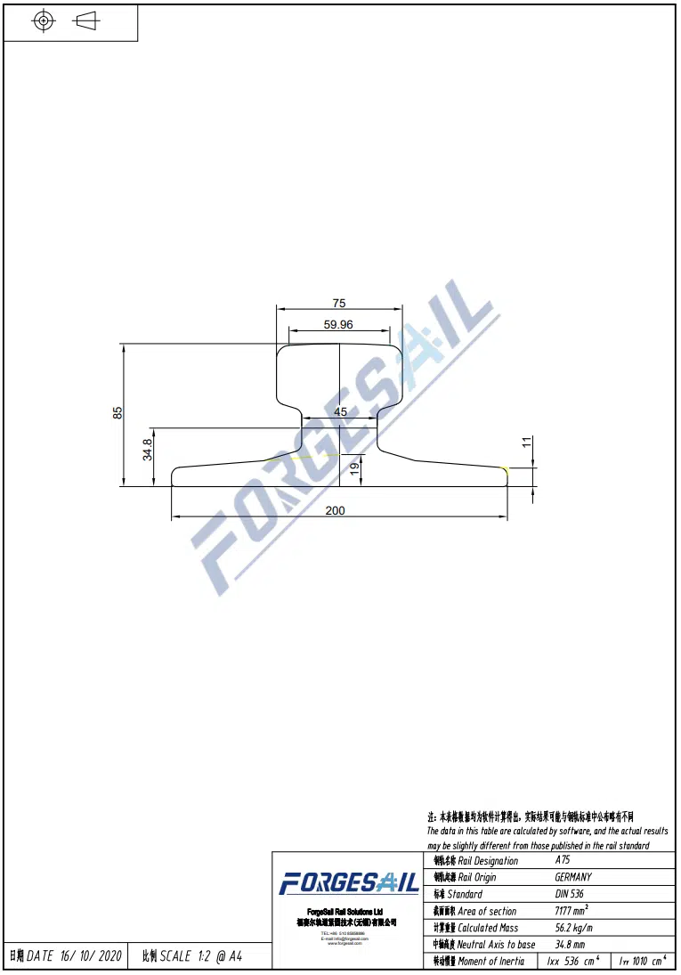
Can one forged rail clip fit both DIN 536 A series and GB QU crane rails?
No. The rail base contour differs between DIN A and GB QU series. Clip nose geometry must match the exact rail profile to maintain full contact area and avoid lateral shift failure. Always verify clip compatibility with the specific rail standard before installation.