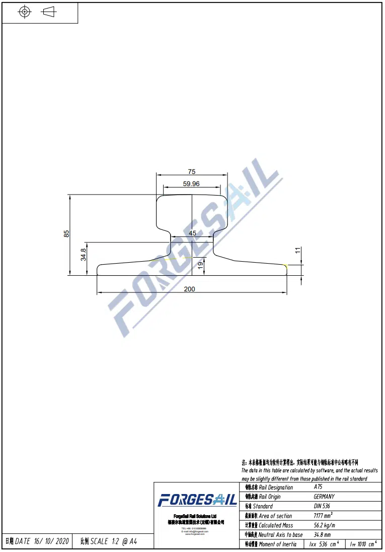




Heavy-Duty Crane Rail Installation best practices define the long-term safety, stability and service lifespan of all heavy-duty industrial track systems, whether you construct shipyard gantry crane runways, automated warehouse crane tracks or heavy-load workshop overhead crane rail projects. A properly installed crane rail system is the foundation of safe and efficient material handling. Whether you’re building a new gantry crane runway in a shipyard or upgrading an automated warehouse, installation quality directly determines track lifespan, crane performance, and — most importantly — workplace safety. This guide walks through the critical phases of industrial crane rail installation, from pre-installation planning to final alignment verification with standardized industry specifications.
1.Pre-Installation Planning for Heavy-Duty Crane Rail Installation
1.1 Load Analysis and Rail Selection
Before any rail touches the foundation, you need answers to three core planning questions:
- Maximum wheel load: What is the heaviest load the crane will lift, and how is that load distributed across the wheels?
- Crane classification: Is this a Class A (light duty) or Class F (continuous severe duty) crane? Higher classifications demand tighter tolerances and more robust fastening.
- Operating environment: Indoor or outdoor? Temperature extremes? Corrosive atmosphere (marine, chemical)?
The rail profile — whether DIN 536 A-series crane rail, JIS, ASCE, or Chinese GB QU-series — must be selected based on the wheel load analysis. For heavy-duty applications like shipyard Goliath cranes, profiles such as DIN 536 A150 or QU120 are common.
For detailed parameter data of DIN & QU crane rails, view our Crane Rail Product Specification Page
1.2 Foundation Inspection
The concrete foundation or steel support structure must be inspected before rail installation:
- Concrete must have reached full design strength (typically 28-day cure)
- Surface flatness should be within ±3 mm over any 3-meter length
- Anchor bolt positions verified against the rail layout drawing
- Any cracks, spalling, or irregularities documented and addressed
Pitfall: Installing rails on an uncured foundation is a leading cause of premature sole plate settlement and rail misalignment.
2. Sole Plate Installation in Heavy-Duty Crane Rail Installation
2.1 Setting Out
Mark the centerline of each rail runway using a total station or precision theodolite. For long runways (100m+), establish control points every 10-15 meters to maintain alignment accuracy.

2.2 Levelling and Grouting
The standard method uses epoxy-based precision grout (such as Forgesail’s high-strength epoxy grout) poured between the sole plate and the concrete foundation:
- Position sole plates on adjustable levelling shims
- Adjust each plate to design elevation within ±1 mm
- Build formwork around each plate
- Pour epoxy grout and allow to cure per manufacturer specifications (typically 24-72 hours)
- Torque anchor bolts to specified values after grout has cured
Installation quality also depends on the fabricated steelwork around the rail system. Support brackets, guards, and other ancillary plate components need to be formed accurately so they fit without excessive shimming, distortion, or field rework. For contractors that produce these parts in-house, JS RAGOS heavy-duty press brakes are built for large-tonnage plate forming, with CNC control and crowning to help maintain consistent angles across long workpieces.

Why epoxy grout? Compared to cementitious grout, epoxy grout offers:
- Higher compressive strength (80-100+ MPa)
- Better impact and vibration resistance
- Chemical resistance in harsh environments
- No shrinkage during curing
Check our fastening accessories introduction: Rail Sole Plate & Rubber Pad

3. Rail Placement & Precision Alignment for Standard Crane Rail Installation
3.1 Rail Handling
Crane rails are heavy — a 12-meter length of A150 rail weighs approximately 1,800 kg. Use appropriate lifting equipment and never drop or drag rails, which can introduce micro-fractures.
3.2 Alignment Tolerances
The following tolerances should be maintained for heavy-duty crane runways (reference: CMAA 70, FEM 1.001, and GB/T 10183):
| Parameter | Standard Tolerance | Precision Application |
|---|---|---|
| Gauge (span between rails) | ±5 mm | ±3 mm |
| Rail straightness (horizontal) | ±2 mm / 2m | ±1 mm / 2m |
| Rail level (vertical) | ±3 mm / 10m | ±2 mm / 10m |
| Joint gap (thermal expansion) | 2-5 mm | Per design spec |
| Joint step (vertical mismatch) | ≤0.5 mm | ≤0.3 mm |
| Joint step (horizontal mismatch) | ≤0.5 mm | ≤0.3 mm |
Review detailed CMAA alignment tolerance guides at Spanco Official Runway Guide
3.3 Rail Joint Methods
There are three main approaches to connecting rail sections:
- Bolted Fishplate Joints: Traditional, economical, and easy to maintain. Best for light-to-medium duty and applications where the rail might need to be replaced sectionally.
- Thermite (Aluminothermic) Welding: Produces a continuous, seamless joint with strength matching the parent rail. Preferred for heavy-duty applications and automated systems where smooth crane travel is critical. Forgesail’s thermite welding kits include pre-measured portions, moulds, and ignition systems for field use. Browse our full thermite welding kits: Rail Thermite Welding Tools
- Flash Butt Welding: Shop-based process producing the strongest joints. Typically used for rail lengths pre-welded before delivery to site.

4. Rail Fastening System Installation Under Crane Rail Installation Standards
4.1 Clip Installation Sequence
- Place the rail pad on the sole plate surface (if specified). The pad absorbs vibration and reduces wear.
- Position the rail on the pad, centered between the clip mounting points.
- Install base clips on both sides, finger-tight initially.
- Use a calibrated torque wrench to tighten bolts to the design specification — typically 200-400 N·m for forged steel clips in heavy-duty applications.
- Verify that each clip applies consistent clamping force without pinching the rail (which would prevent thermal expansion).

4.2 Adjustable vs. Fixed Clips
Forgesail’s adjustable forged steel rail clips allow fine positioning adjustment during installation — a significant advantage when dealing with real-world foundation tolerances. The rubber nose on each clip provides controlled elasticity, maintaining clamping force even as the rail undergoes thermal cycling.
5. Post-Installation Quality Verification of Crane Rail Installation
5.1 Post-Installation Survey
After all rails are installed and fastened, perform a complete survey:
- Gauge measurement: At every joint and at 5-meter intervals along straight sections
- Elevation survey: Digital level or laser scanner, recording every 2-3 meters
- Straightness check: Piano wire or optical alignment, both vertical and horizontal planes
- Clip torque verification: Random sample check of 10-20% of all clips
5.2 Load Testing
Before commissioning, conduct a load test:
- Static load test: 125% of rated capacity, hold for 10+ minutes
- Dynamic load test: 110% of rated capacity, full range of crane travel
- Rail deflection monitoring: Measure rail deflection under load — should not exceed design limits (typically L/600 for heavy-duty runways)
5.3 Documentation
Record all as-built measurements, deviations, and corrective actions. This documentation is essential for future maintenance reference, quality validation and local regulation compliance.
6. 5 Common Installation Mistakes to Avoid During Crane Rail Installation
- Skipping foundation inspection: The best rail system cannot compensate for a failing foundation.
- Over-torquing anchor bolts: Can crack the concrete or strip threads. Always use a calibrated torque wrench.
- Ignoring thermal expansion: Rails expand approximately 0.012 mm per meter per degree Celsius. A 100m rail in a 40°C temperature swing expands nearly 48 mm. Joint gaps are not optional.
- Inadequate joint alignment: Even a 1 mm step at a joint causes impact loading that accelerates wheel and rail wear.
- Rushing grout cure time: Applying full load before epoxy grout reaches design strength permanently compromises the installation.
7. Professional Manufacturer Support for Complex Crane Rail Installation Projects
For complex or high-value installations, bringing in the rail system manufacturer’s engineering team provides several advantages:
- System-level design: The manufacturer understands how rails, clips, pads, and sole plates interact as a system
- Installation supervision: On-site guidance ensures correct clip positioning, torque values, and joint treatment
- Documentation: As-built records, inspection reports and torque logs handed over at completion
Forgesail provides complete design and installation support for crane rail projects worldwide. Our engineering team has experience with installations ranging from 50-ton automated warehouse systems to 1,600-ton Goliath gantry cranes.
Conclusion
Heavy-Duty Crane Rail Installation is a precision engineering task that rewards careful planning and disciplined execution. The difference between a track that lasts 5 years and one that lasts 25 years often comes down to the quality of alignment, grouting, and fastening during the initial installation.
At Forgesail, we manufacture the complete rail fastening system — rails, clips, sole plates, pads, buffer stops, grouts, and welding kits — and provide engineering support from design through commissioning. Contact our team to discuss your next project.
Have questions about your specific rail installation? Contact Forgesail’s engineering team →
Contact: info@forgesail.com | Tel: +86-17768339068 | forgesail.com