


A150 Crane Rail System is one of the most reliable heavy-duty track solutions for modern industrial facilities. In ports, shipyards, steel plants, and large-scale industrial facilities, the performance of a crane rail system directly determines operational safety, maintenance cost, and long-term reliability.
The DIN 536 A150 crane rail is a core component of a robust A150 Crane Rail System, designed for demanding environments with continuous operation, high wheel loads, and strict alignment requirements. This technical insight provides an engineering-focused overview of A150 crane rail specifications, material properties, manufacturing process, fastening system. Explore our DIN 536 crane rail profiles design, and a real project application case for the complete A150 Crane Rail System — backed by our crane rail fastening systems.
1. A150 Crane Rail Profile for Heavy-Duty Applications
The A150 crane rail profile is engineered for high-load crane systems where load distribution, fatigue resistance, and structural stability are critical.

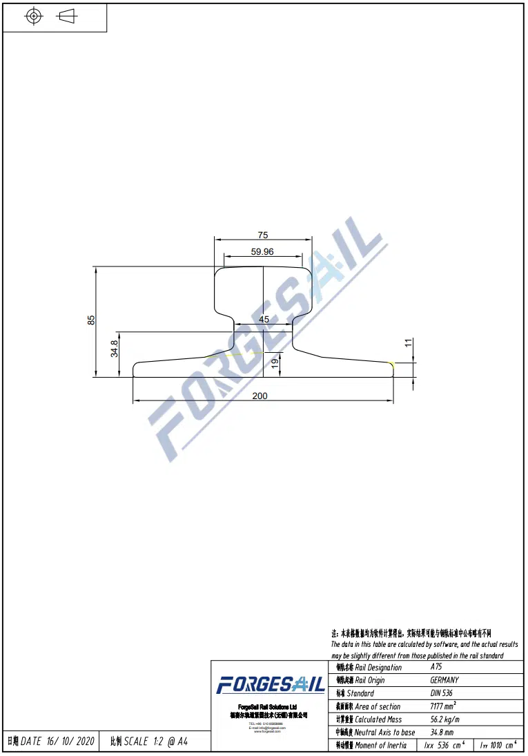
Key Dimensions (DIN 536 Standard)
| Parameter | Value (mm) |
| Rail Height | 150 |
| Head Width | 150 |
| Web Width | 80 |
| Base Width | 220 |
| Weight | ~150 kg/m |
The wide rail head significantly reduces wheel-to-rail contact stress, improving fatigue resistance and extending service life in high-duty crane operations.
In heavy industrial environments, rail geometry directly affects:
- Crane travel stability
- Wheel wear rate
- Alignment retention over time
2. Material Engineering: U71Mn High-Strength Rail Steel
The DIN 536 A150 crane rail is manufactured from U71Mn manganese steel, optimized for high wear resistance and structural durability under cyclic loading.
Engineering Properties
- High tensile strength for load-bearing performance
- Controlled yield strength for deformation resistance
- High hardness for wear resistance under wheel contact
- Balanced ductility for impact absorption
These properties make A150 suitable for:
- High wheel load crane systems
- Repetitive heavy-duty operations
- Long-span crane rail installations
3. Manufacturing Process: Hot-Rolled Precision Rail Production
A150 crane rails are produced through a controlled hot rolling process to ensure structural integrity and dimensional consistency.
Process Flow
- Continuous casting billet preparation
- High-temperature reheating
- Multi-pass rolling forming process
- Controlled cooling for microstructure stability
- Straightening and ultrasonic inspection
This ensures:
- Consistent rail geometry across long lengths
- Stable metallurgical structure
- Reliable mechanical performance in field conditions

4. Industrial Applications of A150 Crane Rail Systems
The A150 crane rail system is widely used in heavy industrial infrastructure where high reliability and load capacity are required.
Typical Applications
- Container terminals and port crane rail systems
- Shipyard gantry crane tracks (including Goliath cranes)
- Steel mills and continuous casting workshops
- Heavy fabrication and assembly plants
- Automated logistics and material handling systems
Operating Conditions
- High wheel loads exceeding 300 kN
- Continuous duty cycles (24/7 operations)
- Long-span crane travel systems
- High structural vibration environments

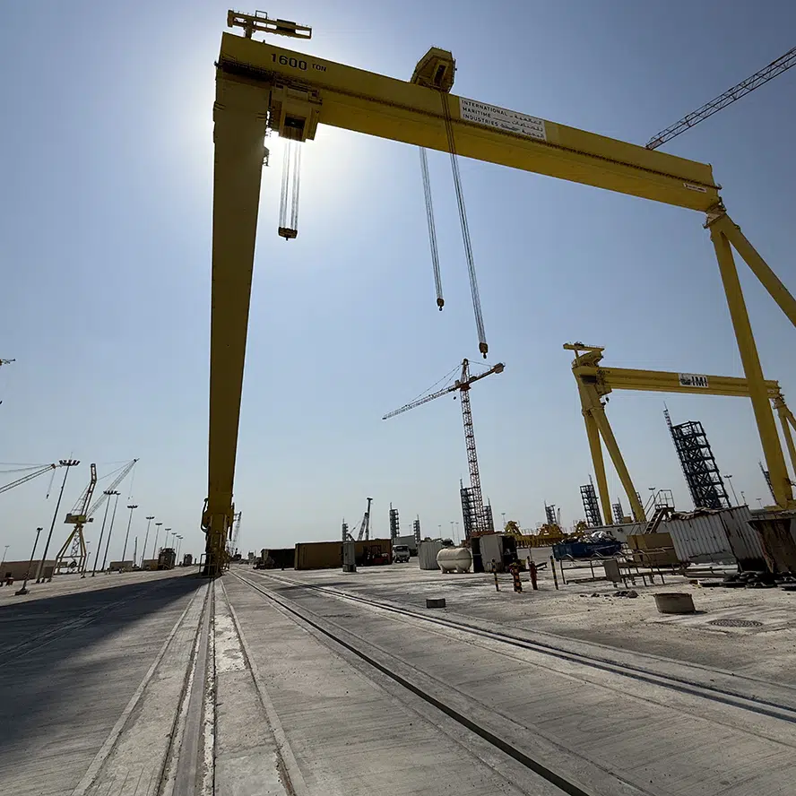
ForgeSail heavy-duty rail solution for a 1,600-ton Goliath gantry crane at Saudi Aramco’s KSICMS/MYP project.
5. Crane Rail System Engineering: Fastening and Support Design
A high-performance crane rail system requires more than the rail profile itself. The system performance depends heavily on rail fastening and structural support design.

Core System Components
Rail Clips (Fastening Systems)
Rail clips secure the rail laterally while allowing controlled longitudinal movement caused by thermal expansion and crane dynamic loads.
System types include:
- Welded rail clips
- Bolted fastening systems
- Adjustable alignment clips
- Elastic vibration-reducing systems
Rail Pads
Rail pads are installed between rail and support structure to improve load distribution and reduce vibration transmission.
Functions include:
- Impact load absorption
- Stress redistribution
- Noise and vibration reduction
Base Plates (Sole Plates)
Base plates provide a precision interface between rail and supporting structure, ensuring:
- Accurate installation level
- Stable load transfer
- Structural alignment control
- For base plates and other custom metal components that require accurate dimensions and mounting features, precision CNC machining can help achieve consistent tolerances and reliable fit during assembly.
Anchor Bolt Systems
Anchor bolts secure the crane rail system to concrete or steel foundations, ensuring stability under dynamic crane loads.
A properly engineered fastening system directly improves:
- Rail alignment stability
- System fatigue resistance
- Maintenance cycle reduction
6. Engineering Selection Criteria for A150 Crane Rail Systems
When designing or selecting a crane rail system, key engineering parameters include:
- Maximum wheel load and dynamic load factors
- Crane duty classification and operating frequency
- Structural support conditions (concrete or steel beam)
- Environmental exposure (corrosion, temperature variation)
- Installation tolerances and alignment accuracy
Poor alignment control is one of the most common causes of:
- Accelerated rail wear
- Wheel flange damage
- System vibration issues
7. PROJECT CASE STUDY: Heavy-Duty Crane Rail System for Goliath Crane Application
Project Overview
A complete DIN 536 A150 crane rail system was engineered and supplied for a heavy-duty Goliath gantry crane application in a large-scale industrial project in the Middle East.
The system was designed for:
- Ultra-high wheel loads
- Long-span crane operation
- Continuous heavy-duty cycles
- Strict alignment and settlement control
Engineering Challenges
The project required solving several critical engineering constraints:
- Long-distance rail alignment over large structural spans
- Foundation settlement compensation
- High dynamic impact loads from crane operation
- Strict tolerance requirements for rail straightness and levelness
System Solution
The final crane rail system included:
- DIN 536 A150 crane rails
- High-performance rail fastening system
- Elastomer rail pads for vibration control
- Precision base plate leveling system
- Engineered anchor bolt foundation fixation
Engineering Outcome
The implemented system achieved:
- Stable crane travel performance under full load
- Reduced rail wear rate under cyclic operation
- Improved alignment retention over long-term operation
- High reliability under continuous industrial duty
This project demonstrates that crane rail performance is not only determined by the rail profile, but by the entire engineered system design approach.
8. Conclusion: A150 Crane Rail as a Complete Engineering System
The DIN 536 A150 crane rail system is a proven solution for heavy industrial applications requiring high load capacity, long service life, and engineering reliability.
Its performance is defined by:
- Robust rail geometry
- High-strength material properties
- Precision manufacturing process
- Integrated fastening system design
For port, shipyard, and heavy industrial crane infrastructure, A150 remains a benchmark solution for long-term operational stability.
Engineering Consultation & Project Support
If you are planning a crane rail installation project or sourcing a complete crane rail system solution, our engineering team can support your design and procurement process.
- Crane rail system design and selection support
- DIN 536 A150 rail supply and technical specification guidance
- Rail fastening system engineering (clips, base plates, pads, anchor systems)
- Project-based technical consultation for EPC and industrial clients
Contact us to ensure your crane rail system is engineered for performance, alignment stability, and long-term operational reliability.
For a detailed guide on crane rail types and specifications →Read the full guide