



Understanding Crane Rail Damage
Crane rails operate under repetitive concentrated loading that leads to characteristic damage patterns. Unlike mainline railway rails where speed is the primary stress factor, rail damage is driven by wheel load magnitude, cycle count, and environmental conditions. Early detection of crane rail damage through systematic inspection is the most effective way to prevent unplanned downtime and avoid catastrophic rail failure.
This guide classifies crane rail damage into 9 types, adapted from railway industry standards and crane-specific failure data. Each damage type is described with its root cause, inspection method, and recommended action threshold.Refer to our crane rail maintenance checklist for inspection frequency recommendations.
Damage Type: Rail Head Wear
Vertical and side wear
Rail head wear is the progressive loss of material from the rail running surface due to wheel-rail contact. In crane tracks, vertical wear is measured at the center of the rail head; side wear occurs on the gauge corner from wheel flange contact during crane acceleration and braking.
Root causes: High wheel loads, frequent acceleration/braking cycles, misaligned crane wheels, and inadequate lubrication.
Inspection method: Measure vertical head height loss using a rail wear gauge or digital caliper at 10 m intervals. Record measurements in mm and plot wear rate over time.
Threshold: Replace rail when vertical head wear exceeds 10-15% of the original head height, or when side wear creates a gauge-corner radius smaller than the wheel fillet radius.
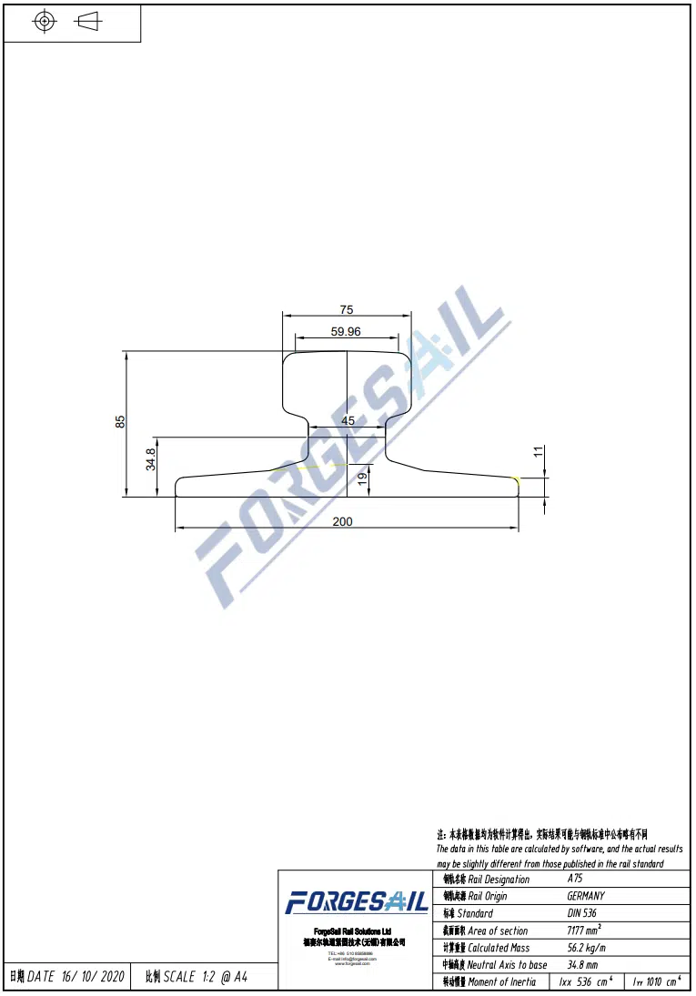
Note: A75 rail head 45mm → 10-15% = 4.5-6.75mm wear limit

Damage Type: Surface Spalling and Flaking
Peeling of the rail head surface
Spalling is the detachment of thin metal flakes from the rail running surface due to rolling contact fatigue. It appears as shallow craters or depressions on the rail head.
Root causes: High contact stresses exceeding material yield strength, surface work hardening beyond ductility limits, and pre-existing micro-cracks from manufacturing or grinding.
Inspection method: Visual inspection. Spalling craters deeper than 2 mm should be recorded by length, width, and depth. Photograph for comparison on subsequent inspections.
Threshold: Spalling exceeding 10% of the rail head surface area or individual craters deeper than 3 mm requires rail replacement or grinding.
Note: Check condition of rail clips in the affected area for increased vibration

Crane Rail Damage Type: Wheel Burn and Gauging
Localized surface damage from wheel slip
Wheel burn occurs when crane wheels slip on the rail during acceleration or braking, generating localized heat that transforms the rail head microstructure into brittle martensite. This creates a hard, brittle zone prone to cracking.
Root causes: Sudden acceleration or braking, low wheel-rail adhesion (wet/oiled rails), and mismatched wheel diameters.
Inspection method: Daily operator visual check for discolored patches. Hardness testing may be performed where wheel burn is suspected. Use a hardness tester to identify the hardened zone.
Threshold: Wheel burn patches deeper than 1 mm or showing evidence of crack formation should be ground out immediately. Track clip torque in the affected section should be verified.
Note: Apply proper acceleration/deceleration control settings

Crane Rail Damage Type: Rail End Deformation (Battered Ends)
Plastic deformation at rail joints
Battered rail ends occur at fishplated joints where wheel impact loads repeatedly deform the rail end. Additional causes include vertical mismatch between adjacent rail ends (step), loose fishplates, and crane wheel flats that amplify joint impact forces. This creates a downward slope at the joint that accelerates wear on both the rail and crane wheels.
Root causes: Excessive expansion gap width, loose or corroded fishplate bolts, and wheel flat spots.
Inspection method: Run a straight edge along the rail top through the joint. Measure the gap between straight edge and rail surface. Use a step gauge to measure vertical mismatch between rail ends.
Threshold: Battering depth exceeding 3 mm or vertical mismatch exceeding 2 mm at the joint requires rail end grinding or joint rebuilding.
Note: Welded joints (aluminothermic) eliminate mechanical joints and reduce end battering

Crane Rail Damage Type: Corrugation (Wavy Wear)
Periodic undulations on rail head
Corrugation is the formation of periodic waves on the rail running surface, typically with wavelengths of 30-80 mm (short pitch) or 80-300 mm (long pitch). It causes increased vibration, noise, and accelerated component fatigue.
Root causes: Resonance between the crane structure and track system, inadequate damping from rail pads, insufficient track stiffness, wheel/rail creep forces, uneven rail joint alignment, and wheels with out-of-round profiles.
Inspection method: Run a straight edge along the rail and use a feeler gauge to measure wave trough depth. Measure wavelength between peaks.
Threshold: Short-wave corrugation (30-80 mm wavelength): grinding required when depth exceeds 0.3 mm over a 1 m straight edge. Long-wave corrugation (80-300 mm wavelength): grinding required when depth exceeds 1.5 mm. If corrugation returns within 12 months, investigate wheel condition, rail pad specification, and joint alignment.
Note: Rail pads with adequate damping properties help reduce corrugation formation

Crane Rail Damage Type: Surface Cracks (Head Checks, Gauge Corner Cracks)

Fine cracks on rail head
Surface cracks develop at the gauge corner of the rail head due to repeated wheel-rail contact stress exceeding the material’s endurance limit. These cracks typically propagate at 10-15 degrees to the rail axis.
Root causes: Excessive contact stress, wheel flange contact, inadequate lubrication, and surface work hardening.
Inspection method: Visual inspection after cleaning the rail head. Use dye-penetrant testing (DPT) or magnetic particle inspection (MPI) for crack detection. Measure crack length and angle from rail axis.
Threshold: Shallow surface cracks (depth <2 mm, length <10 mm) can be removed by grinding if sufficient head height remains. Cracks exceeding 2 mm depth, cracks at the rail web or base, or cracks showing branching require immediate rail replacement regardless of length. Cracks at multiple locations within a 10 m section indicate systemic overloading.
Note: Regular NDT inspection is recommended for heavy-duty crane tracks

Crane Rail Damage Type: Internal Rail Defects
Subsurface fatigue cracking
Internal defects originate below the rail surface due to shear stress concentration at the wheel-rail contact interface. These include shelling (subsurface horizontal cracks) and transverse defects (vertical crack propagation that can lead to sudden rail breakage).
Root causes: High cyclic shear stress, material inclusions from manufacturing, and rail head material exceeding its fatigue limit.
Inspection method: Ultrasonic testing (UT) using a rail flaw detector. Internal defects are invisible to visual inspection and require NDT equipment.
Threshold: Internal defects detected by UT must be classified by type and size: small point-like indications (inclusions, porosity) below 2 mm equivalent flaw size can be monitored at quarterly intervals; cracks, large-area delaminations, or transverse defects exceeding 2 mm require immediate rail replacement. For critical tracks (CMAA Class E-F), annual UT is commonly recommended.
Note: Internal cracks can propagate suddenly — UT screening is essential for safety
Crane Rail Damage Type: Rail Deformation
Bent rail, web buckling,
Rail deformation includes bending in the vertical or horizontal plane, web buckling, and local distortion. Unlike wear or cracks, deformation affects the rail’s load-bearing geometry.
Root causes: Thermal expansion against fixed restraints, foundation settlement, inadequate expansion gaps, and impact overload from crane operation errors.
Inspection method: Daily operator visual check for visible curvature, kinks, or buckles. Quarterly laser alignment survey for quantitative measurement. Any visible buckling is a safety-critical condition requiring immediate shutdown. LOTO procedures must be followed before approaching the track.
Threshold: Horizontal deviation exceeding 2 mm over a 2 m base length, or total deviation exceeding 10 mm over the full runway length (ISO 12488 Class 1). Any visible web buckling requires immediate shutdown and engineering assessment.
Note: Proper sole plate grouting prevents foundation settlement deformation
Crane Rail Damage Type: Rail Corrosion
Section loss from oxidation
Corrosion reduces the effective cross-section of the rail, weakening its bending strength and creating stress concentration sites at corrosion pits. It affects the rail base, web, and head depending on the environment.
Root causes: Coastal salt spray, chemical exposure in industrial plants, condensation in enclosed runways, and galvanic corrosion at clip-rail contact points.
Inspection method: Visual grading: Grade 1 (surface rust, <5% section loss), Grade 2 (moderate pitting, 5-15% section loss), Grade 3 (severe, >15% section loss). Measure pit depth with a pit depth gauge.
Threshold: Replace rail when remaining thickness in any zone falls below minimum: rail head < 70% of original height, web < 80% of original thickness, or rail base < 5 mm minimum remaining thickness. Section loss exceeding 15% in any zone triggers a detailed assessment; do not rely on percentage alone. Grade 2 rails should be scheduled for replacement within 12 months.
Note: Hot-dip galvanized rail clips and corrosion-protected fastening components help reduce corrosion around the fastening system

Inspection Methods Comparison
Each crane rail damage type requires a specific inspection technique. The following table summarizes the recommended methods and intervals:
| Damage Type | Primary Inspection Method | Frequency | Typical Detection Capability |
| Head wear | Wear gauge / digital caliper | Monthly | 0.1 mm |
| Spalling | Visual + depth gauge | Monthly | 1 mm depth |
| Wheel burn | Visual + hardness test | Weekly | Surface discoloration |
| Battered ends | Straight edge + feeler gauge | Quarterly | 0.5 mm gap |
| Corrugation | Straight edge + surface profilometer | Quarterly | 0.05 mm |
| Surface cracks | Dye-penetrant (DPT) or MPI | Quarterly | 0.5 mm crack length |
| Internal defects | Ultrasonic testing (UT) | Annually | 2 mm diameter flaw |
| Deformation | Laser alignment survey | Quarterly | 1 mm deviation |
| Corrosion | Visual grading + pit depth gauge | Quarterly | 0.5 mm pit depth |
For detailed inspection procedures and equipment specifications, refer to CMAA Specification #70 or ISO 12488.
When to Replace Crane Rail
Crane rail replacement decisions should be based on the most severe damage type present. Replacement criteria are subject to project specifications, crane manufacturer requirements, and applicable standards (CMAA, ISO 12488, EN, port authority). The values in this guide are typical ranges — the governing specification should always take precedence. The most restrictive criterion among wear, crack, corrosion, and deformation limits should govern the replacement decision.
Damage is managed through a three-tier approach: Tier 1 — monitor only (minor damage, continue regular inspection); Tier 2 — scheduled repair (plan grinding or section replacement within 3-6 months); Tier 3 — immediate replacement (severe damage, stop crane operation).
| Damage Condition | Replace When |
| Vertical head wear | >10-15% of original head height, or side wear exceeds gauge corner limit — whichever is reached first |
| Side (gauge) wear | Gauge corner radius < wheel fillet radius |
| Surface cracks | Crack length >5 mm or branching present |
| Internal defects | Cracks, delaminations, or transverse defects >2 mm on UT |
| Corrosion section loss | >15% in any zone |
| Deformation | >2 mm deviation over 2 m base length, or >10 mm total runway |
| Rail break / full section fracture | Immediately |
ForgeSail Products & Support
ForgeSail manufactures crane rails, rail clips, sole plates, rail pads, and fastening systems for all major crane rail standards. For the products referenced in this guide:
Crane rail profiles — technical specifications, drawings, and ordering information.
Welded and bolted rail clips — technical specifications, drawings, and ordering information.
Rail pads and sole plates — technical specifications, drawings, and ordering information.
Crane rail maintenance checklist — technical specifications, drawings, and ordering information.
Contact the ForgeSail engineering team for damage assessment support, replacement recommendations, and custom solutions.
Related guides: Crane Rail Installation Guide | Crane Rail Welding Guide
Frequently Asked Questions
u003cstrongu003eHow often should crane rails be inspected for damage?u003c/strongu003e
Visual checks daily, wear measurements monthly, surface crack inspection quarterly, and ultrasonic testing annually. Heavy-duty tracks (CMAA Class E-F) may require more frequent NDT screening.
u003cstrongu003eWhat is the most common crane rail damage type?u003c/strongu003e
Rail head wear is the most common, followed by surface cracks at the gauge corner. Corrosion accelerates all other damage types in coastal environments.
u003cstrongu003eCan surface cracks be ground out, or must the rail be replaced?u003c/strongu003e
u003cstrongu003eCan surface cracks be ground out, or must the rail be replaced?u003c/strongu003eu003cbru003eSurface cracks up to 2 mm depth can typically be removed by grinding, provided the rail still has sufficient remaining head height. Cracks exceeding 5 mm depth or showing branching require rail replacement.
u003cstrongu003eHow does crane rail damage differ from railway rail damage?u003c/strongu003e
Railway rails experience high-speed dynamic loading where speed and impact dominate. Crane rails experience slow, repetitive concentrated loading where cycle count and wheel load magnitude are the primary damage drivers
u003cstrongu003eWhat role do rail clips play in preventing rail damage?u003c/strongu003e
Properly torqued rail clips maintain uniform contact pressure, prevent rail movement, and reduce vibration — all of which slow the progression of head wear, corrugation, and surface crack formation.
u003cstrongu003eCan head-hardened rail reduce wear?u003c/strongu003e
Yes. Head-hardened rail (350-400 HB surface hardness) typically provides 2-4x longer service life than standard carbon rail (260 HB) in curves and heavy-haul applications. The higher hardness resists gauge-corner wear and surface fatigue. However, head-hardened rail requires matched wheel profiles and adequate suspension to avoid accelerated cracking.
u003cstrongu003eCan crane rails be repaired by welding?u003c/strongu003e
Generally no. The rail running surface is a work-hardened, high-carbon component. Conventional welding on the running surface creates brittle zones that crack under wheel load. Surface defects should be repaired by grinding or section replacement. Welding may be acceptable on non-wearing surfaces such as the rail web or base, subject to a qualified welding procedure.